LINK GPS MGMT DATA 3 GHz Carrier Backhaul Radio Model: AF-3X DATA MGMT GPS LINK
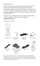
Introduction Thank you for purchasing the Ubiquiti Networks® airFiber® 3 GHz Carrier Backhaul Radio. This Quick Start Guide is designed to guide you through the installation, show you how to access the airFiber Configuration Interface, and explain how to set up an airFiber link. This Quick Start Guide is for use with the airFiber AF-3X. Warranty terms, safety notices, and compliance information are in the airFiber AF-3X User Guide, available at: downloads.ubnt.
Installation Requirements The airFiber AF-3X radio is designed for use with the airFiber X AF-3G26-S45 antenna. Other Requirements • • • • Clear line of sight between airFiber radios Clear view of the sky for proper GPS operation Vertical mounting orientation Mounting point: • At least 1 m below the highest point on the structure • For tower installations, at least 3 m below the top of the tower • Ground wires – min. 10 AWG (5 mm2) and max. length: 1 m.
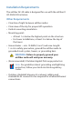
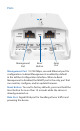
Hardware Overview Chain 0: Connects to + 45° on airFiber Antenna LED Panel Connects to External GPS Antenna LINK GPS MGMT DATA Port Cover Chain 1: Connects to - 45° on airFiber Antenna
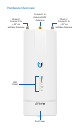
Ports Management Port Reset Button Data Port Management Port 10/100 Mbps, secured Ethernet port for configuration. In-Band Management is enabled by default in the airFiber Configuration Interface. When In-Band Management is disabled, the MGMT port is the only port that can monitor, configure, and/or update firmware. Reset Button To reset to factory defaults, press and hold the Reset button for more than 10 seconds while the device is already powered on.
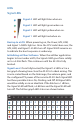
LEDs Signal LEDs Signal 4 LED will light blue when on. Signal 3 LED will light green when on. Signal 2 LED will light yellow when on. Signal 1 LED will light red when on. Bootup to airOS When powering on, the Power, GPS, LINK, and Signal 1-4 LEDs light on. Once the CPU code takes over, the GPS, LINK, and Signal 1-3 LEDs turn off. Signal 4 LED remains on to indicate the boot sequence is underway.
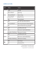
Additional LEDs LED LINK GPS State Status Off RF Off Short Flash* Syncing Normal Flash* Beaconing Long Flash* Registering On Operational Off No GPS Synchronization Normal Flash* Non-Operational (Weak Signal) On Operational (Strong Signal) Off No Ethernet Link MGMT On DATA Ethernet Link Established Random Flashing Ethernet Activity Off No Ethernet Link On Ethernet Link Established Random Flashing Ethernet Activity Off No Power On Powered On * Short Flash (1:3 on/off cycle
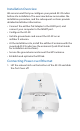
Installation Overview We recommend that you configure your paired AF-3X radios before site installation. The overview below summarizes the installation procedure, and the subsequent sections provide detailed installation information. • Connect the airFiber PoE Adapter to the DATA port, and connect your computer to the MGMT port. • Configure the AF-3X. • Install a ground wire and mount the AF-3X on an airFiber X antenna.
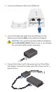
2. Connect an Ethernet cable to the DATA port. 3. Connect the Ethernet cable from the DATA port to the Ethernet port labeled POE on the airFiber PoE Adapter. WARNING: Use only the included airFiber PoE Adapter, Model: GP-H240-100G-4. Failure to do so can damage the unit and void the product warranty. 4. Connect the Power Cord to the power port on the airFiber PoE Adapter. Connect the other end of the Power Cord to a power source.
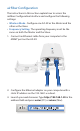
airFiber Configuration The instructions in this section explain how to access the airFiber Configuration Interface and configure the following settings: • Wireless Mode Configure one AF-3X as the Master and the other as the Slave. • Frequency Setting The operating Frequency must be the same on both the Master and the Slave. 1. Connect an Ethernet cable from your computer to the MGMT port on the AF-3X. 2. Configure the Ethernet adapter on your computer with a static IP address on the 192.168.1.x subnet. 3.
4. The login screen will appear. Enter ubnt in the Username and Password fields. Select your Country and Language. You must agree to the Terms of Use to use the product. Click Login. Note: U.S. product versions are locked to the U.S. Country Code to ensure compliance with FCC regulations. 5. The Main tab will appear. Click the Tools drop-down and select Link Calculator. This tool will guide you on how to best minimize bandwidth and power/interference issues. 6.
8. Configure the Basic Wireless Settings: a. For one AF-3X, select Master as the Wireless Mode. For the other AF-3X, keep the default, Slave. b. Enter a name in the Link Name field. This should be the same on both the Master and the Slave. c. If needed, change the Channel Bandwidth, (Master) Duty Cycle, Output Power and/or Maximum Modulation Rate settings. 9. Configure the Frequency Setting. The selected Frequency must be the same on both airFiber radios. 10. Configure the Wireless Security: a.
12. In-Band Management is enabled by default, so each airFiber radio must have a unique IP Address. (If the airFiber radios use the same IP Address, you may lose access to the airFiber radios via the DATA ports.) Click the Network tab. a. For the Management IP Address option: -- DHCP Keep the default, DHCP, to use DHCP reservation on your router to assign a unique IP Address. -- Static Change the IP Address, Netmask, and other settings to make them compatible with your network. b.
Hardware Installation Install a Ground Wire 1. Remove the nut from the Ground Bonding Point located on the back of the AF-3X. Ground Bonding Point 2. Attach a ground wire (min. 10 AWG or 5 mm2) to the lug and replace the nut to secure the wire. 3. At the installation site, secure the other end of the ground wire to a grounded mast, pole, tower, or grounding bar. WARNING: Failure to properly ground your airFiber radio will void your warranty.
Mount to the airFiber X Antenna 1. Attach the AF-3X to the mounting bracket. a. Align the mounting tabs on the back of the AF-3X with the mounting bracket. b. Slide the AF-3X down to lock it into place.
2. Attach the RF cables from the antenna feed to the RF connectors on the AF-3X in this combination: + 45° to Chain 0 and - 45° to Chain 1. 3. Attach the External GPS Antenna to the RF connector labeled GPS. Then place the magnetic External GPS Antenna on the bracket (this is temporary; you will mount the External GPS Antenna on the GPS Antenna Mount at the site).
4. Attach the protective shroud. a. Align the hash mark on the top of the shroud with the notch on the dish antenna. b. Rotate the shroud clockwise until it locks into place.
Mount the External GPS Antenna Locate a mounting point that has a clear view to the sky, and is above and as far away as possible from the AF-3X. 1. Attach the GPS Antenna Mount to the pole using the metal strap, or attach it to a wall using the appropriate fasteners (not included). 2. Place the External GPS Antenna on the mount. 3. Secure the cable of the External GPS Antenna to the mount with a Cable Tie.
Connecting Power over Ethernet 1. Lift the release latch on the bottom of the AF-3X and slide the Port Cover off. 2. Connect an outdoor, shielded Ethernet cable to the DATA port.
3. Connect the other end of the cable from the DATA port to the Ethernet port labeled POE on the airFiber PoE Adapter. WARNING: Use only the included airFiber PoE Adapter, Model: GP-H240-100G-4. Failure to do so can damage the unit and void the product warranty. 4. Connect an Ethernet cable from your network to the Ethernet port labeled LAN on the airFiber PoE Adapter. 5. Connect the Power Cord to the power port on the airFiber PoE Adapter. Connect the other end of the Power Cord to a power source.
Mount the PoE Adapter (Optional) 1. Remove the Mounting Bracket from the adapter by sliding the bracket downward. 2. Place the Mounting Bracket at the desired location and mark the holes for the fasteners. Pre-drill the holes if necessary, then secure the bracket to the wall using two fasteners (not included). 3. Attach the airFiber PoE Adapter to the bracket by aligning the four slots and tabs, and then slide the adapter downward.
Surge Protection For added protection, install two surge suppressors, such as the Ubiquiti Ethernet Surge Protector, model ETH-SP, at the end of each link. Install the first surge protector within one meter of the airFiber DATA port, and install the second surge protector at the ingress point of the location housing the wired network equipment. GPS Antenna Max. 1 m AF-3X Mounted on AF-3G26-S45 ETH-SP Ground to Pole, Tower, or Grounding Block: Max.
Alignment Tips • To accurately align the airFiber radios for best performance, you MUST align only one end of the link at a time. • You may need to use additional hardware to compensate for issues such as the improper orientation of a mounting pole or significant elevation differences between airFiber radios. Establishing a Link Adjust the positions of the Master and the Slave to establish a link.
b. Loosen the six elevation bolts, and use the hex nut on the elevation rod to adjust the elevation. Note: Do NOT make simultaneous adjustments on the Master and Slave. 2. Slave Visually aim the Slave at the Master. To adjust the Slave’s position: a. Loosen the four pole clamp nuts, and rotate the airFiber antenna on the pole to align the azimuth. b. Loosen the six elevation bolts, and use the hex nut on the elevation rod to adjust the elevation. 3. Check to see if a link is established.
4. Slave Aim the Slave at the Master to achieve the strongest signal level on the Master. Note: Refer to the Signal LEDs section for details on the signal values. Note: Maximum signal strength can best be achieved by iteratively sweeping through both azimuth and elevation. 5. Master Aim the Master at the Slave to achieve the strongest signal level on the Slave. 6. Repeat steps 4 and 5 until you achieve an optimal link, with all four Signal LEDs solidly lit.
Installer Compliance Responsibility Devices must be professionally installed and it is the professional installer’s responsibility to make sure the device is operated within local country regulatory requirements. The Output Power, Antenna Gain, Cable Loss, and Frequency fields are provided to the professional installer to assist in meeting regulatory requirements.
Specifications airFiber AF-3X Dimensions Weight RF Connectors 224 x 82 x 48 mm (8.82 x 3.23 x 1.89") 0.35 kg (0.
Online Resources Support support.ubnt.com Community community.ubnt.com Downloads downloads.ubnt.com © 2015 Ubiquiti Networks, Inc. All rights reserved. Ubiquiti, Ubiquiti Networks, the Ubiquiti U logo, the Ubiquiti beam logo, airFiber, airOS, RocketDish, and TOUGHCable are trademarks or registered trademarks of Ubiquiti Networks, Inc. in the United States and in other countries. All other trademarks are the property of their respective owners.