
- Ultra Electronics Printers Instructions

3461/07/01 ISSUE 2 PRINTHEAD INSTALLATION & COMMISSIONING SPEC. DCR No. 26106
VI
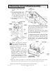
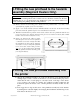
(3) Check that the springs at the back of the printhead assembly are neatly compressed and
are not bulging outwards or inwards. If they are bulging the assembly will have to be
removed and refitted again until they remain neatly compressed.
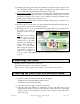
(4) If a head bar was fitted
, refit it with its two securing screws ensuring that the left hand
screw is also fitted through the terminal of the printhead earthing strap (Loctite 222
threadlocker should be used on these screws). Align the terminal downwards and in
parallel with the leading edge of the chassis cover.
If no head bar was fitted
, ensure that the printhead earthing strap is connected to its’
original securing point
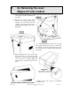
(5) Reconnect the two cables at the rear of the printhead ensuring that the locking arms of
the grey ribbon cable connector are fully engaged.
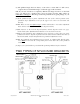
(6) Referring to the rear of the Test Card which was supplied with your new printhead, set
the ‘density hex value’ as
indicated on the rear of the
card.
N.B.
There are two different
diagrams on the rear of the
card (see right), compare the
cicuit board in your printer
against the two diagrams and
decide which diagram is
relevent to your printer.
Then change the settings on
your printer to match those
marked on the diagram on
your card (in the high-lighted area). Do not change any of the unmarked switch
positions.
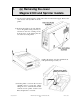
5. Refitting the cover
Refitting of the case is the reverse of removal.
Ensure the printer interior is free of debris or particles.
Take care not to trap the display cable as the top cover is lowered into position.
6. Setting up your new thermal printhead
(1) Load the card cassette with cards and refit into the printer.
On Flip models ensure that UR8 Dye-Film is fitted.
On all other models fit UR1 Dye-Film.
(2) Reconnect the mains supply and switch on the printer.
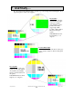
(3) After the printer has finished its initialisation sequence (all lights have stopped
flashing and the printer is silent), press the internal test button at the rear of the printer
(approx 1cm above the Centronics port). After a short delay the printer will start to
print a test image.