MODEL # 02-07-0057 ASSEMBLY INSTRUCTIONS 04-11-11
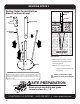
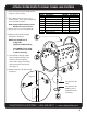
MOUNTING OPTION 1 Footing Detail for Installations Placed on Ground Level Support Post 4lb Hammer Footer Support Post SURFACING (3) Ground Spikes GROUND Instructions: 1. With Footers in position, secure each footer to the ground using Footer (3) ground spikes. NOTE: A 4 lb. hammer may be required to drive spikes into the ground. IMPORTANT: Never install play equipment over hard, unresilient surfaces such as asphalt, concrete or compacted earth.
MOUNTING OPTION 2 Footing Detail for Installations Requiring Concrete Footers Support Post Footer Support Post SURFACING Footer (3) M10 x20mm ( 3/4”) BHCS Bolts GROUND Footer Instructions: 1. Bolt Footer and Inground Footer together using (3)M10 x 20mm(3/4”) BHCS Bolts, and M10 Lock Nuts.
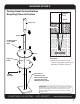
MOUNTING OPTION 2 DETAIL 12"(305mm) Diameter x 18”(457mm) Deep Holes (4 ) Places NOTE: Hole depths indicated on all ground plans are measured from the finished surface. See Footing Details. 28”(711mm) All Footer dimensions are based on level finished surface. 53”(1246mm) 45”(1143mm) Concrete Required : Approx. .18 Cubic Yards (.14 Cubic Meters) NOTE: Suggested Min.
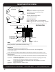
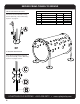
ATTACH FOOTER POSTS TO CRAWL TUNNEL AND FOOTERS 1. Lower U-shaped Support Post(B) behind flange of Crawl Tunnel(A). 2. Insert Bolt(D) through center hole in Crawl Tunnel(A), into Support Post(B) and secure with Barrel Nut(E). NOTE: Lightly tighten Bolts(D) until all Bolts(D) have been inserted. D E F G 3. Repeat Step 2 for remaining Bolts(D). 4. Align hole in Support Post(B) with hole in Footer(C).
SECURE CRAWL TUNNEL TO GROUND ABOVE GROUND INSTALLATION For Above Ground installation using Ground Spikes(A), refer to Mounting Option 1 on page 2. Parts List Letter Description Quantity A Ground Spikes 12 B In-Ground Footer 4 Hardware Complete 1 C 12 M10 x 20 BHCS Bolt D M10 Lock Nut 12 Part Number 02-07-0048 02-07-0049 33-12-0058 33-11-0002 33-11-0400 A or IN-GROUND INSTALLATION For In-Ground installation using the In-ground Footer(B), refer to Mounting Option 2 on pages 3 and 4.