Parts Manual Mfg. No: 030710-00 6,500 Watt Brigg & Stratton EPA Copyright © Briggs and Stratton.
Table Of Contents Model Components Page Control Panel (80024618). . . . . . . . . . . . . . . . . . . . . . . . . . . . . . . . . . . . . . . . . . . . . . . . . . . . . . . . . . . . . . . . . . . . . . . . . . . . . . Main Unit (80024617). . . . . . . . . . . . . . . . . . . . . . . . . . . . . . . . . . . . . . . . . . . . . . . . . . . . . . . . . . . . . . . . . . . . . . . . . . . . . . . . . Wheel Kit (80006254). . . . . . . . . . . . . . . . . . . . . . . . . . . . . . . . . . . . . . . . . . . .
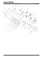
Control Panel (80024618) Note: Unless noted otherwise, use the standard torque specifications r o u F d t o o r N ep R Copyright © Briggs and Stratton. All Rights reserved i t c 4 Mfg.
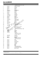
Control Panel (80024618) REF NO PART NO 1 707256 2 3 4 5 6 7 8 9 10 11 12 13 14 15 16 17 18 19 20 319458GS 319477GS 319476GS 319459GS 191481GS 704025 43437GS 704903 312636GS 704907 319525GS 707288 707290 198245GS 319530GS 319529GS 709526 706326 703804 QTY DESCRIPTION PANEL-CONTROL -(Includes Ref. No.
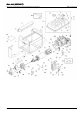
Main Unit (80024617) Note: Unless noted otherwise, use the standard torque specifications r o u F d t o o r N ep R Copyright © Briggs and Stratton. All Rights reserved i t c 6 Mfg.
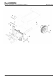
Main Unit (80024617) REF NO PART NO 1 707302 2 3 4 5 6 7 8 9 10 11 12 13 14 15 16 17 18 19 20 21 22 23 24 25 26 27 28 29 30 31 32 33 34 35 36 37 38 39 40 41 42 43 44 45 46 47 707249 703804 705635 706159 704183 314440GS 704192 705909 703805 312005GS 189137GS 703264 707301 704142 319456GS 708881 704331 202997GS 705772 319587GS QTY DESCRIPTION CRADLE -(Includes Ref. Nos.
Main Unit (80024617) Note: Unless noted otherwise, use the standard torque specifications r o u F d t o o r N ep R Copyright © Briggs and Stratton. All Rights reserved i t c 8 Mfg.
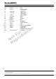
Main Unit (80024617) REF NO PART NO 48 49 50 705783 707297 791745 51 52 209417GS 315017GS 53 54 55 56 57 58 59 60 61 62 63 64 900 707295 207879GS 709931 314955GS 709939 189134GS 705771 709940 708880 706535 709941 QTY 24G032-0007-G1 DESCRIPTION TERMINAL BLOCK BOLT KIT-FUEL HOSE -(Cut to Fit) VALVE-FUEL HOSE-VAPOR -(Cut to Fit) BAND-STATOR BOOT NUT CLAMP BOLT GROMMET COVER-RUBBER WIRE BRACKET-AIR CLEANER PAD-RUBBER COVER-ALT SCREW-FLANGE M6 X 8 ** ENGINE r o u F d t o o r N ep R i t c n o Footno
Wheel Kit (80006254) Note: Unless noted otherwise, use the standard torque specifications r o u F d t o o r N ep R Copyright © Briggs and Stratton. All Rights reserved i t c 10 Mfg.
Wheel Kit (80006254) REF NO PART NO 1 2 3 4 5 6 7 8 9 10 11 12 13 14 15 16 17 18 19 319396GS 319360GS 319361GS 75477GS 318677GS 96716GS 49820GS 207825GS 319453GS 319452GS 319454GS 319285GS QTY 67989GS 704198 703813 704145 22247GS 316510GS DESCRIPTION HANDLE GRIP-HANDLE GRIP-HANDLE SCREW BOLT WASHER NUT BOLT KNOB SPRING PIN MOUNT-VIBRATION * BOLT, M8-1.25 x 16 NUT SUPPORT-LEG AXLE WHEEL WASHER PIN-HAIR r o u F d t o o r N ep R i t c n o Footnotes: * Items without part numbers are common fasteners.
Wiring Diagram (80023875wd) Note: Unless noted otherwise, use the standard torque specifications r o u F d t o o r N ep R Copyright © Briggs and Stratton. All Rights reserved i t c 12 Mfg.
Wiring Diagram (80023875wd) REF NO --- PART NO QTY WARNING DESCRIPTION Wiring Diagram Only Warning Generator Voltage Could Cause Electrical Shock or Burn Resulting in Death Or Serious Injury. To Avoid Electrical Shock Or Burn Hazard, Please Refer Service To Qualified Personnel. r o u F d t o o r N ep R Copyright © Briggs and Stratton.
Wiring Schematic (80023875ws) Note: Unless noted otherwise, use the standard torque specifications r o u F d t o o r N ep R Copyright © Briggs and Stratton. All Rights reserved i t c 14 Mfg.
Wiring Schematic (80023875ws) REF NO --- PART NO QTY WARNING DESCRIPTION Wiring Schematic Only Warning Generator Voltage Could Cause Electrical Shock or Burn Resulting in Death Or Serious Injury. To Avoid Electrical Shock Or Burn Hazard, Please Refer Service To Qualified Personnel. r o u F d t o o r N ep R Copyright © Briggs and Stratton.
Hardware Identification & Torque Specifications Torque Specification Chart Torque Specification Chart FOR STANDARD METRIC MACHINE HARDWARE (Tolerance ± 20%) Property Class 5.6 8.8 Class 5.6 Class 8.8 in/lbs Size Of Hardware ft/lbs M3 M4 M5 M6 M7 M8 M10 M12 M14 M16 M18 M20 M22 M24 M27 M30 M33 M36 M39 5.88 13.44 26.4 44.64 5.2 7.7 15 26 42 64 89 126 169 217 320 435 590 759 988 10.9 Nm. Nm. in/lbs ft/lbs .56 1.28 2.50 4.3 7.1 10.5 21 36 58 88 121 171 230 295 435 590 800 1030 1340 13.44 30.72 60.
Copyright © Briggs and Stratton.