
Full Product Manual


7
Check for parts online at www.ioniceaugers.com or call 800-345-6007 M-F 8-5 CT
Operator's Manual
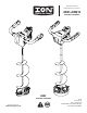
ION® Electric Ice Augers
BATTERY
RETAINING
STRAP
(STEP 2)
LITHIUM BATTERY
(STEP 1)
INDICATOR
LIGHT
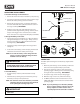
Reverse Switch Operation
To use reverse operation function to ush hole of unwanted
debris do as follows: SEE FIGURE 4
1. To activate reverse function, depress the reverse switch
and then depress the operating lock and operating
trigger at the same time.
2. To stop auger release the operating trigger.
To Flush a hole, do as follows:
1. Place the auger half way down the hole with the auger
starting in the hole. The top of the auger ight must be
above the water and slush.
2. Activate reverse function and continue to lower the
auger into the hole. The lower ring of the auger must exit
the bottom of the hole.
3. After a few seconds of reverse operation, release the
operating trigger.
NOTE: KEEP POWERHEAD CLEAR OF WATER. Water will
come back up the hole and overow.
4. Repeat the above steps three times to clear the hole.
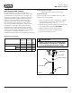
Battery Charging and Monitoring
1. Remove the battery retaining strap by pulling it towards
the motor. SEE FIGURE 5
2. Remove the battery by sliding it o of the powerhead.
3. Plug the charger into a 110/240AC outlet.
4. Slide the battery into the charger.
5. The charge indicator light should blink green.
SEE FIGURE 6
6. When indicator light is lit solid green, the battery is fully
charged.
7. Once the battery has been fully charged, unplug the
charger from the wall.
8. Remove the battery from the charger.
NOTE: Recharging the battery after each use is best for
the life of the battery.
9. Place the battery back onto the powerhead when ready
to use.
NOTE: Battery should be o of the powerhead when not
in use.
10. Pull the battery retaining strap back over battery.
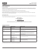
Charger Indicator Lights and Meaning
ACTION/COLOR MEANING
Flashing green Battery charging
Solid green Battery fully-charged
Flashing red Battery too hot
Solid red Battery too cold
OPERATING
LOCK
LEVER
OPERATING
TRIGGER
OPERATING
TRIGGER
OPERATING
LOCK
LEVER
FIGURE 3
ION ION X
REVERSE SWITCHREVERSE SWITCH
FIGURE 4
FIGURE 5
FIGURE 6
ION ION X
ION ION X