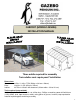
CARPORT (MODEL# 455006) INSTALLATION MANUAL Three adults required for assembly Trois adultes sont requis pour l’installation Dimensions: Overall: 16.5ft x 11.83ft x 7.75ft (503cm x 361cm x 236cm) Base: 14.83ft x 11.67ft (451cm x 355cm) Interior: 10.75ft x 6.33ft to 6.92ft clearance (328cm wide x 193 to 211cm) Tools required (not provided): 6ft (1.
11.83ft x 16.5ft / 3.61m x 5.03m Carport Instruction Manual IMPORTANT: RETAIN FOR FUTURE REFERENCE, READ CAREFULLY Consult with your local governing authority / local municipal codes regarding installation of temporary structures before purchase or assembly. Some jurisdictions may require permits for, or otherwise regulate, installation and use.
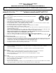
PART QTY (11-741) LEG POST A 6 (11-757) FLOOR BRACKET B (11-755) LEFT LEG BRACKET C (11-756) RIGHT LEG BRACKET D (11-748) GUTTER JUNCTION E (11-746) RIGHT GUTTER E-1 (11-747) LEFT GUTTER E-2 (13-041) GUTTER END PLATE F-1 (13-042) GUTTER END PLATE F-2 (11-749) TRUSS JUNCTION H PART DIAGRAM PART (11-742) RIGHT ROOF TRUSS H-1 QTY 3 12 (11-743) LEFT ROOF TRUSS H-2 3 6 (11-753) CENTER MID BEAM I 1 6 (11-752) CENTER BEAM I-1 2 2 (11-760) CENTER BEAM PLATE I-2 2 2 (11-754) BEAM JUNCTION J 3
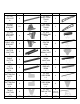
(11-744) MAIN RAFTER O (11-767) ROOF PANEL P 69” X 28” (11-768) BOLT M (11-779) NUT M-1 (11-777) WASHER Q-1 (11-783) BOLT S (11-784) WASHER S-1 (11-785) ACORN NUT S-2 (11-773) BOLT T (11-782) BOLT U (11-775) WASHER V (11-769) ACORN NUT W 12 (packed inside leg) (11-770) BOLT X 14 M6x16mm (11-774) WASHER X-1 M6 (14-044) BOLT X-2 40 +4 spare 142 +5 spare 72 +4 spare M8 12 +1 spare M10*25mm 24 +2 spare M10 12 +1 spare M10 24 +1 spare M8*100mm 36 +3 spare 84 +3 spare M6x16mm 102 +4 spare 1/4
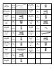
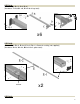
STEP 01A: (Pieces: A x6, B x12, C x6, D x6) (Hardware: T x24, Q-1 x48, W x24 for 6 legs total) x6 STEP 01B: (Pieces: E x2, E-1 x2, E-2 x2, F-1 x2, F-2 x2, silicone for sealing (not supplied) ) (Hardware: X x24, X-1 x24, M-1 x24 for 2 gutters total) SILICONE x2 STEP 01C: 5
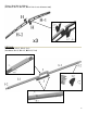
(Pieces: H x6, H-1 x3, H-2 x3) (Hardware: S x12, S-1 x24, S-2 x12 for 3 sets of braces total) x3 STEP 01D: (Pieces: I x1, I-1 x2, I-2 x2, J x1) (Hardware: X x12, X-1 x12, M-1 x12, Y x4) 6
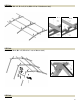
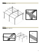
STEP 01E: (Pieces: L x2, L-1 x4, L-2 x4, J x2) (Hardware: X x24, X-1 x24, M-1 x24, Y x4 for 2 side beams total) x2 STEP 02: (Hardware: X-2 x6, X-1 x6, V x4, M-1 x6) X-2 X-2 7
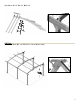
STEP 03: (Hardware: X-2 x12, X-1 x12, V x8, M-1 x12 for 2 side beams total) X-2 X-2 STEP 04: (Hardware: U x6, Q-1 x12, W x6 for 3 sets of braces total) STEP 05: 8
(Hardware: X x12, X-1 x12, M-1 x12) STEP 06: (Hardware: U x6, Q-1 x12, W x6 for 3 sets of braces total) 9
STEP 07: (Hardware: X x12, X-1 x12, M-1 x12) STEP 08: (Hardware: M x16, M-1 x16) 10
STEP 09: (Pieces: N x4, O x12) N STEP 10: At this point, verify that each of the legs is vertical and correctly located, and securely tighten any bolts that have been left loose.
STEP 11: (Pieces: P x14) 12
STEP 12: (Hardware: M x12 into end rafters; M x12 into main rafters; M-1 x24) M M M-1 M L-1 L-1 M-1 STEP 13: Anchor the unit as appropriate to your foundation. Anchoring hardware and tools not supplied with this unit.
STEP 14: (Hardware: Aa x56; Aa-1 x56; Aa-2 x56 for 14 roof panels total) Aa-1 Aa-2 Aa MAINTENANCE NOTES 14
1. In case of a defective or damaged part, or for any other questions concerning the product, please contact the manufacturer directly. 2. Please have the parts list and part numbers on hand when ordering or requesting replacement parts. 3. The product should not be installed adjacent to trees or a sloped roof. Snow and ice may slide onto the roof and cause it to collapse. 4. While the product is designed for 4 seasons use, the snow must be cleared from the roof on a regular basis.
ABRI D’AUTO (MODÈLE # 455006) GUIDE D’INSTALLATION Dimensions: Global: 16.5pi x 11.83pi x 7.75pi (503cm x 361cm x 236cm) Base: 14.83pi x 11.67pi (451cm x 355cm) Intérieur: 10.75pi x 6.33pi à 6.92cm de clairance (328cm large x 193 à 211cm de clairance) Outils requis (pas inclus): Escabeau 6pi (1.
Guide d’installation IMPORTANT: GARDEZ POUR RÉFÉRENCE FUTURE, LISEZ ATTENTIVEMENT Consultez avec votre gouvernement ou municipalité locale concernant l’installation de structures temporaires avant l’achat ou l’assemblage. Certaines juridictions peuvent requérir un permit, ou autrement règlementer, leur installation et utilisation.
PIÈCE QTÉ (11-741) POTEAU A 6 (11-757) CROCHET DE BASE B (11-755) SUPPORT GAUCHE C (11-756) SUPPORT DROIT D (11-748) JOINTURE DE GOUTTIÈRE E (11-746) GOUTTIÈRE DROITE E-1 (11-747) GOUTTIÈRE GAUCHE E-2 (11-758) PLAQUE DE GOUTTIÈRE F-1 (11-759) PLAQUE DE GOUTTIÈRE F-2 (11-749) JOINTURE D’ARCHE H PIÈCE SCHÉMA PIÈCE (11-742) MOITIÉ D’ARCHE DROITE H-1 QTÉ 3 12 (11-743) MOITIÉ D’ARCHE GAUCHE H-2 3 6 (11-753) MI-POUTRE CENTRALE I 1 6 (11-752) POUTRE CENTRALE I-1 2 2 (11-760) PLAQUE CENTRALE I-2
(11-744) CHEVRON PRINCIPAL O (11-767) PANNEAU DE TOIT P (11-768) BOULON M (11-779) ÉCROU M-1 (11-777) RONDELLE Q-1 (11-783) BOULON S (11-784) RONDELLE S-1 (11-785) ÉCROU BORGNE S-2 (11-773) BOULON T (11-782) BOULON U (11-775) RONDELLE V (11-769) ÉCROU BORGNE W 12 (emballé dans poteau) (11-770) BOULON X 14 M6x16mm (11-774) RONDELLE X-1 M6 (14-044) BOULON X-2 40 +4 spare 142 +5 spare 72 +4 spare M8 12 +1 spare M10*25mm 24 +2 spare M10 12 +1 spare M10 24 +1 spare M8*100mm 36 +3 spare 84 +3 sp
(Pièces: A x6, B x12, C x6, D x6) (Quincaillerie: T x24, Q-1 x48, W x24 pour 6 poteaux total) x6 ÉTAPE 01B: (Pièces: E x2, E-1 x2, E-2 x2, F-1 x2, F-2 x2, silicone pour le scellage (non-inclus) ) (Quincaillerie: X x24, X-1 x24, M-1 x24 pour 2 gouttières total) SILICONE x2 20
ÉTAPE 01C: (Pièces: H x6, H-1 x3, H-2 x3) (Quincaillerie: S x12, S-1 x24, S-2 x12 pour 3 arches total) x3 ÉTAPE 01D: (Pièces: I x1, I-1 x2, I-2 x2, J x2) (Quincaillerie: X x4, X-1 x4, M-1 x4 pour centre; X x8, X-1 x8, M-1 x8 pour bouts; Y x4 pour plaques) 21
ÉTAPE 01E: (Pièces: L x2, L-1 x4, L-2 x4, J x2) (Quincaillerie par poutre: X x4, X-1 x4, M-1 x4 pour centre, X x8, X-1 x8, M-1 x8 pour bouts, Y x2 pour plaques; 2 poutres total) x2 ÉTAPE 02: (Quincaillerie: X-2 x4, X-1 x4, V x4, M-1 x4 pour les bouts; X-2 x2, X-1 x2, M-1 x2 pour centre) X-2 X-2 22
ÉTAPE 03: (Quincaillerie: X-2 x12, X-1 x12, V x8, M-1 x12 pour 2 poutres total) X-2 X-2 ÉTAPE 04: (Quincaillerie: U x6, Q-1 x12, W x6 pour 3 arches total) 23
ÉTAPE 05: (Quincaillerie: X x12, X-1 x12, M-1 x12) ÉTAPE 06: (Quincaillerie: U x6, Q-1 x12, W x6 pour 3 arches total) 24
ÉTAPE 07: (Quincaillerie: X x12, X-1 x12, M-1 x12) ÉTAPE 08: (Quincaillerie: M x16, M-1 x16) 25
ÉTAPE 09: (Pièces: N x4, O x12) N ÉTAPE 10: À ce point, vérifiez que chaque poteau soit vertical et correctement positionné, et serrez tout les boulons qui ne l’ont pas été encore.
ÉTAPE 11: (Pièces: P x14) 27
ÉTAPE 12: (Quincaillerie: M x12 dans chevrons finals; M x12 dans chevrons principaux; M-1 x24) M M M-1 M L-1 L-1 M-1 ÉTAPE 13: Ancrez l’unité de façon appropriée à votre fondation. La quincaillerie et les outils pour l’ancrage ne sont pas inclus avec ce produit.
ÉTAPE 14: (Quincaillerie: Aa x56; Aa-1 x56; Aa-2 x56 pour 14 panneaux total) Aa-1 Aa-2 Aa 29
NOTES D’ENTRETIEN 1. En cas de pièces défectueuses ou endommagées, ou pour questions concernant le produit, veuillez contacter le manufacturier directement. 2. Ayez, s’il-vous-plait, le nom et numéro de pièce en main quand vous commandez des pièces de remplacement. 3. Ne placez pas l’abri en dessous d’un arbre ou la pente d’un toit de maison. La neige ou la glace pourrai glisser et causer le gazebo de s’effondrer. 4.