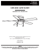
Item #1004 751 910 Item #1002 269 802 #1002 269 803 Model #AL383LED-BK Model #AL383LED-BN #AL383LED-WH USE AND CARE GUIDE HUGGER 52 IN. CEILING FAN Questions, problems, missing parts? Before returning to the store call Home Depot Customer Service 8 a.m. - 7 p.m., EST, Monday-Friday, 9 a.m. - 6 p.m., EST Saturday 1-877-527-0313 HOMEDEPOT.
Table of Contents Table of Contents .......................................................... 2 Operation ......................................................................15 Pull Chain Operating Instructions ...........................................15 Reverse Switch Operating Instructions ..................................15 Safety Information ......................................................... 3 Warranty .........................................................................
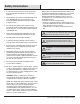
Safety Information 1. To reduce the risk of electric shock, ensure electricity has been turned off at the circuit breaker or fuse box before beginning. 2. All wiring must be in accordance with the National Electrical Code “ANSI/NFPA 70-1999” and local electrical codes. Electrical installation should be performed by a qualified licensed electrician. 3. The outlet box and support structure must be securely mounted and capable of reliably supporting a minimum of 35 lbs (15.9 kg) or less.
Warranty We warrant the fan motor to be free from defects in workmanship and material present at time of shipment from the factory for a period of 15 years after the date of purchase by the original purchaser. We agree to correct such defects without charge or at our option replace with a comparable or superior model if the product is returned. To obtain warranty service, you must present a copy of the receipt as proof of purchase. All costs of removing and reinstalling the product are your responsibility.
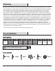
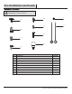
Pre-Installation (continued) HARDWARE INCLUDED NOTE: Hardware not shown to actual size.
Pre-Installation (continued) PACKAGE CONTENTS A B C D F E G Quantity Part Description Quantity A Mounting plate 1 E Blade arm 5 B Fan motor assembly 1 F Light kit 1 C Motor housing 1 G Glass shade 1 D Blade 5 Part Description 6
Installation MOUNTING OPTIONS WARNING: To reduce the risk of fire, electric shock, or personal injury, mount the fan to an outlet box marked acceptable for fan support using the screws provided with the outlet box. An outlet box commonly used for the support of lighting fixtures may not be acceptable for fan support and may need to be replaced. If in doubt, consult a qualified electrician.
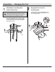
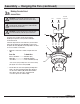
Assembly — Hanging the Fan 1 2 Attaching the mounting plate to the electrical box □ WARNING: To reduce the risk of fire, electric shock or other personal injury, mount the fan only to an outlet box or supporting system marked acceptable for fan support and use the mounting screws provided with the outlet box. □ Hanging the fan from the mounting plate Carefully lift the fan motor assembly (B) and insert the T section of the mounting bar (MM) into the slot in the mounting plate (A).
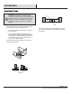
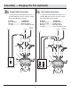
Assembly — Hanging the Fan (continued) 3a Making the electrical connections WARNING: To avoid possible electrical shock, be sure electricity is turned off at the main fuse box before wiring. Hot Neutral Black White Ground conductor WARNING: Check to see that all connections are tight, including ground, and that no bare wire is visible at the wire nuts (except for the ground wire).
Assembly — Hanging the Fan (optional) 3b Single Switch Connections □ 3c Dual Switch Connections □ On a single switch the fan and light can be turned on or off together. Make wire connections as follows, using the wire nuts (BB). Wall switch not included.
Assembly — Hanging the Fan (continued) 4 5 Finishing the fan installation □ □ Swing the motor assembly (B) up into position under the mounting plate (A). Secure the mounting bar (MM) to the mounting plate (A) with the screws and lock washer (CC) provided. Attaching the motor housing to the mounting plate Carefully lift the motor housing (C) onto the mounting plate (A), properly align the holes and tighten the motor housing (C) with the four screws and lock washer (DD) supplied.
Assembly — Attaching the Fan Blades 6 Attaching the blades to the blade arms 7 □ Attach the blades (D) to the blade arms (E) using the three blade attachment screws and fiber washers (AA). Start a screw and fiber washer (AA) into the blade arm (E), but do not tighten. □ Repeat for the two remaining blade attachment screws and fiber washers (AA). □ Tighten each screw securely starting with the center screw. Make sure the blade (D) is straight. □ Repeat these steps for the remaining blades (D).
Assembly — Installing the Light Kit Attaching the light kit to the switch housing 8 9 CAUTION: Before starting installation, disconnect the power by turning off the circuit breaker or removing the fuse at the fuse box. Turning power off using the fan switch is not sufficient to prevent electric shock. NOTE: If you do not wish to install the light kit, skip steps 8 through 9 and proceed to step 10. □ Remove the three light kit mounting screws (FF) from the light kit (F) and keep these screws.
Assembly — Installing the Light Kit (continued) 10 Installing the fan without the light kit (optional) □ Disassemble the switch housing cover (NN) from the light kit (F). You can keep the light kit (F) for future use. □ Attach the plastic plug (II) to the switch housing cover (NN). □ Install the switch housing cover (NN) to the switch housing with light kit mounting screws (FF) provided.
Operation PULL CHAIN OPERATING INSTRUCTIONS Attach the two pull chains and fobs (JJ) to the pull chains located on the switch housing (OO). Turn on the power and check the operation of the fan. The pull chain controls the fan speed as follows: 1 pull - High, 2 pulls - Medium, 3 pulls - Low and 4 pulls - Off. Speed settings for warm or cool weather depend on factors such as the room size, ceiling height, number of fans, and so on.
Care and Cleaning Do □ Do not Check the support connections, brackets, and blade attachments twice a year. Make sure they are secure. Because of the fan’s natural movement, some connections may become loose over time. It is not necessary to remove the fan from the ceiling. □ Clean your fan periodically. Use only a soft brush or lint-free cloth to avoid scratching the finish. The plating is sealed with a lacquer to minimize discoloration or tarnishing.
Troubleshooting (continued) Problem Solution □ Verify that all blades and blade bracket screws are secure (most fan wobble problems are caused by loose parts). Once the fan is properly installed, run the ceiling fan for 10 minutes to let the fan self-adjust. If wobble occurs after running the fan for 10 minutes, verify blade level using the following process: The fan wobbles.
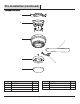
Service Parts A AA F GG B G BB HH CC II C DD JJ D EE E Part FF Description Part Description A Mounting plate AA Blade attachment screw and fiber washer B Fan motor assembly BB Plastic wire nut C Motor housing CC Mounting plate screw and lock washer D Blade DD Motor housing screw and lock washer (preassembled) E Blade arm EE Blade arm screw and lock washer (preassembled) F Light kit FF Light kit mounting screw (preassembled) G Glass shade GG Light holder thumbscr
Questions, problems, missing parts? Before returning to the store call Home Depot Customer Service 8 a.m. - 7 p.m., EST, Monday-Friday, 9 a.m. - 6 p.m., EST Saturday 1-877-527-0313 HOMEDEPOT.COM Retain this manual for future use.