
Full Product Manual

7
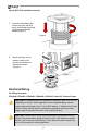
1. Remove pump’s electrical junction box cover and straighten the 2 wires to make
the stripped wire ends accessible outside of the junction box.
2. Screw furnished cable connector into NPT* conduit opening in pump junction box.
3. Strip 6 inches of the outer covering from one end of the furnished electrical cable
being careful not to damage the black and red wire insulation.
4. Loosen cable connector nut and pass the stripped end of the furnished cable
through the cable connector. Tighten the cable connector nut.
5. Strip ½ inch of the insulation from the ends of the red and black cable wires. Using
the furnished wire nuts, connect these wires to the pump wires matching the
colors. Be sure no bare wire is exposed.
6. Fold wires into junction box and replace cover making sure the gasket is in place.
Make sure all screws are seated so there is no space between the cover and the
junction box (see “IMPORTANT!” information box and diagram page 10).
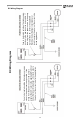
Wiring To A Vehicle Electrical System (see wiring diagram, page 9)
1. Pass the electrical wires to the source of the vehicle power system, supporting the
wires as necessary and protecting them from sharp edges, heat, and anything that
could damage the wires.
2. To determine if the vehicle electrical system is negative (-) or positive (+) ground,
check the battery marking of the terminal that is wired to the vehicle frame or
motor block. The red wire from the pump will connect to positive battery post and
the black wire from the pump will connect to negative battery post.
3. Attach one end of the fuse holder to the end of the ungrounded wire. Make a solid
electrical connection with the other end of the fuse holder to the ungrounded side
of the battery, as close to the battery as possible. Make a solid electrical
connection to the grounded side of the battery with the remaining wire. The battery
terminal or the end of the battery cable is recommended.
4. Check all connections to make sure they are connected per instructions and all
electrical codes. Install the 30 amp fuse (20 amp fuse in 24 VDC installations) in
the fuse holder. The installation is now complete.
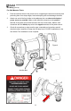
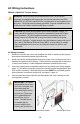
Instructions Before Proceeding With DC Wiring
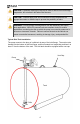
The pump needs to be electrically bonded to supply tank or vehicle frame. To electrically
bond pump, remove green bonding screw located next to junction box cover. Insert this
screw through eyelet of furnished green bonding wire assembly and refasten it securely
to the pump. The other end of the wire is to be stripped of insulation and the bare wire
securely bonded to the vehicle / trailer frame or skid tank.
WARNING! Do not connect the positive or negative power to the green screw or
wire as this could cause a fire.
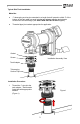
Wiring Instructions (see Figure 4, Page 8)
WARNING! Do not attempt to power the pump from vehicle wiring smaller than
12 gage such as the cigarette lighter wire because these thin wires could
overheat and cause a fire.
*M20 Conduit entry on GE models