Home Control Assistant Version 11 User Guide WWW.HCATech.
The information contained in this document is subject to change without notice. Advanced Quonset Technology, Inc. provides this information “as is” without warranty of any kind, either expressed or implied, but not limited to the implied warranty of mechantability and fitness for a particular purpose. Advanced Quonset Technology, Inc. may improve or change the product at any time without further notice; this document does not represent a commitment on the part of Advanced Quonset Technology, Inc.
Chapter 1 What is the Home Control Assistant? In today’s complex world, busy people can benefit from a home environment that anticipates their needs and helps take care of itself.
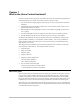
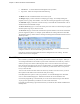
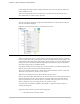
Chapter 1—What is the Home Control Assistant? Quick tour of HCA To start the Home Control Assistant once you have installed it: 1. From the Windows task bar, click the Start button. 2. Choose Programs. 3. Then click Home Control Assistant. The Home Control Assistant window is split into two panes. The left pane, the design pane, shows the HCA design outline with items in the design organized into folders.
Chapter 1—What is the Home Control Assistant? Unlike other Windows programs you may be familiar with (word processors, spreadsheets, email programs), HCA must be running 24/7 on your computer in order to control your home. To make it easier to keep HCA running all the time, and to help prevent you from inadvertently terminating HCA, HCA works a bit differently than these other programs.
Chapter 1—What is the Home Control Assistant? UPB Monitor. A window that shows UPB signals on the powerline Log Viewer. Shows the reception and transmission log The Home menu has commands that take an overview of your The Design Category contains controls for modifying your design. For example, adding new programs, devices, groups, and schedules. Also tools for accessing the properties of your design. The Schedule category contains the controls necessary to work with the Visual Scheduler.
Chapter 1—What is the Home Control Assistant? Using the properties dialog boxes In HCA, nearly everything has properties. Most properties dialog boxes are available from a popup menu that you see when you right click an item in either pane of HCA. In the design pane of the HCA, right click an element word, and choose Properties from the popup menu. The properties dialog box for the item appears.
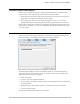
Chapter 1—What is the Home Control Assistant? HCA Properties dialog box You can access the Home Control Assistant Properties dialog box by clicking the HCA menu and choosing Properties. The Home Control Assistant Properties dialog box is a very powerful tool where you can modify or add settings for the general properties for the HCA program.
Chapter 1—What is the Home Control Assistant? The Design Pane The left pane of the HCA Window, called the Design Pane contains a list of the elements of your design. There are a few items not shown and these will be described later. Every object in your design can have a name and most objects require a name. These names appear in the design pane. Each object is also contained within a room or folder. You can have as many objects as you need and place them in as many rooms or folders as you need.
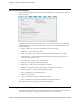
Chapter 1—What is the Home Control Assistant? In this example, the design contains a number of Rooms. One room is for the Entry, another for the Down Bath, and so on. When you open the properties for each object type, on the first tab is the place where you can select which folder or room the object is placed in. Design Pane There are a number of options for sorting the individual folder/room contents and the sorting for the order of the folders displayed.
Chapter 1—What is the Home Control Assistant? The design pane can be organized to show objects within their folders or within their type. Names in HCA are two part where the name is the folder name and the object name taken together. Working within the design pane There are a number of things you can do in the design pane to help create an organization that is best for your use. 1. You can rename a device, program, group, or schedule. Right click on the name and select Rename from the popup menu.
Chapter 1—What is the Home Control Assistant? I n addition to this drag and drop method, you can also choose which displays an icon for an object appears by opening its properties dialog and making changes on the Display tab. What doesn’t appear in design pane Most elements of your design, devices, programs, groups, schedules, and schedule entries, are listed in the design pane.
Chapter 1—What is the Home Control Assistant? Object names As described above, most HCA objects have names. You may use as many characters as you like to name your objects except for dash, left square bracket or right square bracket. There is no practical limit to the length of any name. Printing HCA provides printing support for details on several elements of your design, using a typical Windows format.
Chapter 1—What is the Home Control Assistant? 1. Click the left mouse button. (Unless you’re using a mouse device set up for a left-hander, in which case, you would click the right mouse button.) This is the button that you use most of the time. 2. While you continue to hold the mouse button down, move the mouse pointer to the new location for this object. You will see the object moving with your pointer. 3. When you reach the correct location, release the mouse button.
Chapter 2—HCA Properties Chapter 2 HCA Properties You control the functions of the Home Control Assistant through properties. These properties are accessible though the HCA Application Bubble “HCA Options” button. Because the HCA properties apply to all home designs, you can review or modify them at any time, even when there is no design loaded. This chapter discusses HCA properties and how you set them to control the way the Home Control Assistant works for you.
Chapter 2—HCA Properties About Properties It is important to recognize the difference between properties of HCA and the properties of a particular home design. HCA properties are stored in the Windows registry and your choices are in effect regardless of what home design is loaded. Home design properties are saved in their .HCA files and affect only that design. The following table provides a quick reference on the differences between the two sets of properties.
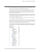
Chapter 2—HCA Properties 2. Click the tab for the properties that you want to view or change. This brings that tab to the front. 3. Make the changes that you want, and click another tab if you want to view or modify other properties. 4. When you are done, click OK to accept the changes and close the dialog box. The new properties will take effect as soon as you click OK. Startup The Startup tab is the first tab on the HCA Properties dialog box.
Chapter 2—HCA Properties This area has five additional options dealing with restart. What these options do is covered in the chapter on Restart. Auto Save The last setting on this property tab tells HCA to automatically save changes (or not) at the time increment that you specify. This is useful so that changes to HCA are kept and not lost in the event of a power failure, or if you forget to save the file.
Chapter 2—HCA Properties Client-Server The client-server tab configures those settings necessary to have HCA operate in client-server mode. This tab appears as: The client-server settings are fully described in the client-server chapter Hardware The HCA properties tab for Hardware is the only place in HCA where you tell HCA about the type of automation hardware connected to your computer. HCA supports from one to four automation interfaces attached to your computer.
Chapter 2—HCA Properties Hint: Not all versions of HCA support all interfaces. See the appendix on HCA versions for an explanation of what version supports which hardware. Also some of these interfaces are designated Legacy Devices and are not normally available unless requested on the Legacy Properties tab. For each interface select the port it is attached to, and what the interface is. Next use the Connect button to confirm that the interface can be sent commands by HCA and process receptions from it.
Chapter 2—HCA Properties Display Pane Another tab of the HCA properties dialog is for the Display pane. While this tab is described here, refer to chapter on displays for a full explanation on how HCA works with displays. Use the Display tab to set properties defining what you see in the display pane (right side) of HCA. The display pane shows the displays you have added to your design, as well as messages. Display Pane Info Tips This section applies only to displays that show icons.
Chapter 2—HCA Properties If you decide you want to change the colors and/or theme for all your displays, folders, and rooms, you can make the changes and then press the “Apply” buttons to make that change.
Chapter 2—HCA Properties Visual Programmer The Visual Programmer is the tool used in HCA to create programs. Programs are a sequence of actions that happen in response to some event. Visual Programs are composed of over 50 different types of actions. Most are general purpose and some are very specific to certain automation interfaces. Working with so many different actions can be daunting.
Chapter 2—HCA Properties Web The web tab is for configuration and setup of the HCA web server. This dialog and the parameters it contains are described in the Web Server chapter. Clock The Clock tab in can help HCA stay punctual. The HCA clock setting facilities are used for those very few PCs that don’t have access to a 24/7 internet connection. If you do have such an internet connection Windows already offers methods to keep the lock up to date and the HCA settings shouldn’t be used.
Chapter 2—HCA Properties This dialog box has extensive instructions, and you may not need any other information on using it. However, here are a few details: Automatic clock correction enabled This checkbox must be checked, or no adjustments will be made to the PC’s clock, regardless of the other settings. Clock is corrected ________ at ___ Select the day of the month and the time that you would like the PC’s clock set.
Chapter 2—HCA Properties You can use this button to override the pre-set time, and make the time check right now. Hint: If you want to use the modem time set feature, after you select the modem and dialing location, use the “Call now” button to make sure that you have your modem configured correctly, and that all works well. The checkbox option “When a time change is noted…” tells HCA to determine the next entry in the current schedule each time the clock on the PC changes.
Chapter 2—HCA Properties Advanced This tab is for several options that control specific features in HCA. Hopefully the text in the dialog should be explanatory as to what these options do. Legacy As time has passed, various automation gear supported by HCA has become less common. In order to reduce the amount of clutter in the User Interface these devices and the supporting user interfaces for their features has been hidden. Enabling options on this tab brings these options back into HCA.
Chapter 2—HCA Properties Extra Features The last tab is a place to enter codes to enable or disable some HCA features. All of them are features that are normally not available as they are very special purpose or intended only for advanced users. Some of these codes are described in various User Guide chapters and Technical Notes.
Chapter 3 Your Home You’ve already read the introduction to the Home Control Assistant and learned about HCA Properties. Now you’re ready to create you own home design in HCA. This chapter tells you how to create a design, and save it in a file. This chapter also discusses simple modifications to your home properties, and security options for your design.
Chapter 3—Your Home The Quick Start Wizard The best way to begin if you are new to home automation or using HCA is the Quick Start Wizard. The purpose of this wizard is to create the start of a home automation solution for your home. The first part of the Wizard is a tutorial to introduce you to the concepts and terms used in later steps. The Wizard then asks questions about your lifestyle and what rooms your home has and asks you to select which lights and appliances to control.
Chapter 3—Your Home The New Home Wizard The Home Control Assistant New Home Wizard helps you set up the new file for your home. Unlike the Quick Start Wizard, this wizard creates an empty design ready for you to add devices, programs, schedules, etc. 1. From the application menu, select New and then File New Wizard. 2. Type in a name for your home design, and click Next. The second step of the wizard displays. 3.
Chapter 3—Your Home Modifying your home file If you want to change the details of your home file you can open the properties dialog. Press the Home Properties button in the ribbon Design category. 1. You can change the name of your home design. When you click OK, the dialog box closes, and the name at the top of the HCA window changes to reflect your change. 2. To make changes to the location click the Location tab. On this tab are additional options not specified when your home design was created.
Chapter 3—Your Home HCA computes sunrise and sunset based upon the location of your home. But this can’t take into account if you home is on a hill – sunrise comes earlier than computed – or in a valley – sunrise comes later. On this tab of the Home Properties you can provide the number of minutes that sunrise and sunset should be adjusted. Then in later uses in schedules when you specify sunrise or sunset the time is computed and then adjusted by the number of minutes specified here.
Chapter 3—Your Home Once set, when anyone attempts to make changes to that element of your home design, a message box appears, and the password must be provided before the properties dialog box displays. As an example, let’s say you entered a password for the design. The next time you want to make changes to the properties for this design, a password message box appears, and you need to type your password before you can change the properties.
Chapter 3—Your Home Light and Dark One of the important things HCA does is to control lighting. It is often useful to know if your home is light or dark to determine if lights should be turned on and at what level. The question “is it light or dark” can be answered by sunrise and sunset time but there are other options. There is the same dialog for Dark and well as Light. While this dialog has many options the general idea is that you determine light from three possible sources.
Chapter 3—Your Home Home Info Also in the Home Properties dialog are three additional tabs that you can use to record information about who created the home design and the home it was created for. Also there is a tab for entering any notes. None of these items are used by HCA. They are just saved in the home design file and can be displayed and edited in the Home Properties dialog. Their use is optional and if used, their use is up to you.
Chapter 4 Devices A “device” is the name HCA gives to real world items – like a switch or module – that it can control. First you “create” the device in HCA using the New Device Wizard. When you create the device in HCA, you give it a name, and other parameters. The New Device Wizard helps you through this process for each device that you want to create for your own home. Then if you need to, you can later modify the properties that you set up when you created each device.
Chapter 4—Devices Planning your devices Before you start creating devices in HCA, it’s a good idea to consider which devices you want to create, where they are, how they work, and how they might work together. You can make it easier to remember and use your device codes with a little consideration as to location and function of the appliances, and by grouping the house and unit codes to match.
Chapter 4—Devices Type in a name for the device and type in or choose one of the already existing folders to store this device. The device name must be unique in the chosen folder. The name you enter can contain most characters, and can be of almost any length. To aid in recognition, you can name devices with descriptions, or location identifiers. For instance, you could name devices: Katie’s night light, dining room chandelier, or Bedroom Lamp 1, 2, and 3.
Chapter 4—Devices In the next step you specify what type of device being created. The choices you have depend upon the manufacturer you select. First select a manufacturer and then select the type of switch or module. Hint: Don't be worried if you don't see exactly the product you have. Many times two parts will have different part number (for example a 600w or a 100w switch) but work the same way. If you don't see exactly what you want just pick something close. In most cases that will be fine.
Chapter 4—Devices The next step for the Wizard depends upon what type of device you are creating. For an Insteon device, in this step you select the address settings. The test button can be used to send an On then an Off command to the selected address. This gives you a quick way to verify that you have selected the correct settings. Now you get to choose the icon that you want to represent this device on a display. The listing includes all device icons provided in the default Icon Theme.
Chapter 4—Devices Modifying an existing device Once a device is created, you can modify any of the properties that you set in the New Device Wizard. You do this in the Properties dialog box for the particular device. There are two ways that you can get to the device properties: 1. Select either: the device icon on a display or the device name in the design pane 2. Click the right mouse button. 3. From the popup menu, select Properties.
Chapter 4—Devices But what about other keypads in your home? Perhaps you have a wireless keypad that you want to be able to take throughout the house and be able to control devices in various rooms. For that to work you would need to set the wireless receiver to some housecode and have all the devices you want to control set to the same housecode. This may be ok, but maybe not. This is where triggers come in handy.
Chapter 4—Devices Display Tab While an icon for this device always appears in the display for the folder than contains it, you can, if you want, place an icon for it on other displays as well. On this tab you can add an icon for the device onto one or more displays. Click the display where you want the icon to appear, click the right arrow , and the display appears in the right list. You can move one, two, or all of your displays to the right column.
Chapter 4—Devices Log Tab The Log tab contains the log for this device. Normally a log entry is added whenever a reception from this device is received or HCA transmits to this device. You may not want to log some devices that generate a lot of traffic. Groups Tab On this tab you can add this device to one or more groups. Groups are more fully covered in their own chapter but, in general, a Group is a set of devices that HCA controls as a unit.
Chapter 4—Devices Schedule Tab HCA contains many different scheduling tools and these are covered in later chapters. In addition to those tools, you can add or remove a schedule entry for a device using this tab. To add a new schedule entry for this device to a schedule, double-click on the “Add new” branch below the schedule. You can add a schedule entry that makes this device go on, go off, or go on then off at a later time.
Chapter 4—Devices References Tab The references tab brings together into one place a report on the use of this device in your design. Devices can be used in many places: schedules, programs, groups, protocol bridges, etc. This provides a quick way to tell where this device is used in case your design becomes complex. Green Tab The Green Tab is where a device is configured in its respond to what the current home mode is. This topic is full cover in the Rooms chapter.
Chapter 4—Devices The X10 Options tab There is very little standardization between device types and manufacturers in the X10 world. This tab allows you to tailor how HCA works with your X10 device. The options listed on the Options tab help you fine-tune the way HCA manages this device. When you selected the type of module or switch in the third step of the wizard, HCA set all these properties as appropriate.
Chapter 4—Devices Option Function Responds to All Lights On command The device turns on if an All Lights On command is sent. Responds to All Lights Off command The device turns off if an All Lights Off command is sent. Note that most inexpensive lamp modules do not support this option. Respond to All Units Off command The device turns off if an All Units Off command is sent.
Chapter 4—Devices Supports automatic status reporting Some devices that can report their status do so whenever they are turned on or off – even if not by an powerline command. This is called automatic status reporting. Enable automatic status reporting If this is checked, HCA programs the device to turn on its automatic status reporting capabilities. Confirm receipt of command sent If the device reports status, HCA can use that to make sure that an ON or OFF command sent to it did get received.
Chapter 4—Devices Insteon Devices Once an Insteon device has been added to your design, when you open its properties dialog Insteon devices have a Linking tab. This tab is fully described in the Insteon appendix.
Chapter 4—Devices UPB Devices UPB Devices are not added to your design using the New Device Wizard. They are imported from a UPB Network definition file. Once added, they do have properties like all other devices. On the UPB Id tab is the information about the UPB device as read from its setup memory. The Options tab for UPB devices is described in the UPB Appendix .
Chapter 4—Devices Final device topics There are two additional topics to discuss with devices. Icon placement As part of the device properties dialog you can select one or more displays to show an icon for the device. If you are using a display with a DXF or picture background you may want to show more than one icon for the device on the display. Perhaps this will make a more realistic appearing floor plan.
Chapter 5 Home Modes Home Modes are a very simple yet powerful system to control devices in your home as your home goes though its day. Let’s assume a normal day as see what you do and how your home can respond. Midnight Asleep 6am You wake up 7:30 am You leave home 6:30 pm You return home 10:30 pm You go to bed OK, so that’s the schedule now let’s see how your devices should respond. TV Most televisions these days are never really off.
Chapter 5—Home Modes The remainder of this chapter will show you how to set your home mode and how to manage devices based upon it. Home Mode HCA displays the current mode in the ribbon Home category. In this screen image the current mode is Home & Awake. To change the current mode, change the selection in the dropdown..
Chapter 5 – Home Modes There are two settings for each mode: “Action when entering mode” and “Response while in mode”. It’s important to understand the distinction. The “Action when entering mode” only happens when HCA shifts from mode to mode. If the current mode is Away and is in that mode for days, nothing g happens. But as soon as the house changes from Away to Home & Awake, then each device is examined to see what should happen when entering the Home & Awake mode.
Chapter 5—Home Modes For Insteon you can use the Visual Scene Editor or the Link button on the linking tab to link the device to HCA so HCA knows when it is locally controlled. Auto off is more fully covered in the chapter on Rooms. Mode Change Triggers While the actions upon entering each mode, as described above, are a powerful too, how does HCA know when you come home, leave home, get up and go to bed? That’s up to you. A common method is to have a keypad that you designate for this.
Chapter 5 – Home Modes Pressing the ‘A’ button when leaving has the button LED show yellow – meaning no one is home. When returning home press the button again and you are home. A similar keypad could be used in the keypad to have a button for go-to-bed and get-up. What if you want to do something more complex? You can always create a program with whatever triggers you want and in that program perform any tests you want and use the Set Home Mode program element to change the mode.
Chapter 5—Home Modes On the properties for those interior lights, mark them like this: When a device is marked as “suspend all actions” for response while in mode, as long as your home is in that mode that device will not be controlled by a schedule or any programs regardless of what the schedule says or the programs does. When you home is in a mode and a device’s actions are suspended in the design pane the device is marked with a slash though it, and in the display pane shown with a green box.
Chapter 6 Rooms Each device, program, and group is stored in a folder. That folder can be a “folder” or a “room”. A folder is simply for organizational purposes. It allows you to have a device, for example, call “Lamp” in one folder and a different device called “Lamp” in another folder. That is really all a folder does. A Room is in many ways similar to a folder except it come with a set of extra semantics. A Room is like a device in that: It can be on or off. I can be scheduled.
Chapter 6—Rooms Rooms on and off A room, like a device, can be ON or OFF. To turn a room on or off, you can right-click the room name in the design pane and select On or Off from the popup menu. When the room is On it shows with a yellow background in the design pane.
Chapter 6—Rooms There are a lot of options on this dialog and they will all be covered in the chapter. For now only the first checkbox is important. If that checkbox is “ticked” then the state of the device participates in determine the room state as described above. Working with rooms Like a device, a room can be scheduled to go on or off at a certain time or, in a program it can be controlled by the On and Off elements.
Chapter 6—Rooms In the same way that a device auto-off is configured, you can have up to three different auto-off specifications. In the above example, 5 minutes after the room is tuned on – when it’s dark – the room goes off. This means that any devices in the room configured to respond when the room goes off, are sent a command to go off. Hint: Even if the devices in the room have their own auto-off specifications, the room auto-off operates independently of device auto-off specifications.
Chapter 6—Rooms Switch settings Here is a timeline of what happens: The room is off. The motion sensor sees you and starts the timer. This is because the motion sensor has the setting enabled to trigger an auto-off specification and that specification says when the room is off and an ON command is received, the timer is started. Since the room goes ON, the light in the room is sent a command to go on.
Chapter 6—Rooms Example 2 In this example there are two lights in the room. Here is what we want to happen: You walk in the room. You turn on one switch An auto off timer starts You turn on a second switch The timer should be canceled because by turning on multiple lights you are saying you want to stay in the room. And since you may turn on either light first, the settings of each light must be the same.
Chapter 6—Rooms Switch settings: Motion sensor settings: Timeline of what happens. You walk into the room and the motion sensor sees you. Since the motion sensor participates in the room state, the room is now on. When the room goes on, the switch is sent a command to go on. As long as the motion sensor sees you the timer keeps getting reset. You change the light level of the switch. The timer is restarted. When the motion sensor next sees you, the switch is not sent a command.
Chapter 7 - Schedules Chapter 7 Schedules and Schedule Entries Now that you’ve created some devices, you might want to set up a schedule or two for the control of them. Controlling devices in your home at various times throughout the day is one of the central uses for the Home Control Assistant. With HCA you can create multiple schedules, each one fitting a different aspect of your home life.
Chapter 7 - Schedules About schedules and schedule entries Creating schedules and schedule entries is a very powerful aspect of HCA. In order for you to take full advantage of the possibilities, you need to understand a few important terms. Term Definition Schedule A schedule tells when things will happen: when devices will turn on and off, when programs will start, and run, what the “plan” for HCA is. A schedule is composed of a list of schedule entries. HCA can contain more than one schedule.
Chapter 7 - Schedules Considering schedules and entries Before creating schedules, it’s best to think a bit about how to organize them. In HCA schedules can be organized in what is called a parent and child relationship. What this is all about is best shown by an example. Suppose in your home you have both outside and inside lights that you want to control. Every day you would like to have the outside lights come on at dusk.
Chapter 7 - Schedules These three examples illustrate the needs for each type of schedule entry: example 1 is a good use for an On entry; for example 2 you would need an Off entry; and for example 3 an On-Off entry would be appropriate. Selecting days When creating a schedule entry, you may be asked to select the day, date, or type of days that you want this schedule entry to apply to. There are several options.
Chapter 7 - Schedules If you choose Vary within 10 minutes, then this entry can happen anywhere between 5:50 p.m. and 6:10 p.m. You can make the time vary by any amount from one to fifty nine minutes. The Vary within amount HCA uses for one day will never be the same as the amount chosen for the previous or next day.
Chapter 7 - Schedules 2. Give the schedule a name and click Next. 3. Decide whether you want this schedule to be the current schedule when HCA is started normally. If so, click the appropriate check box. You can designate only one schedule in your design as the normal start schedule, however, you can change this designation whenever you like. When you have made your choice, click Next.
Chapter 7 - Schedules 4. The next step of the Schedule wizard is to select if this new schedule is to be a parent schedule or a child of another schedule. Once you have created a schedule, you can modify its properties by first selecting the schedule in the design pane, then right click with the mouse and choose Properties from the popup menu. The properties are almost the same as those you created using the wizard. Refer to Modifying an Existing Schedule later in this chapter, for details.
Chapter 7 - Schedules The upper list box contains the devices, programs, and groups in your design. The lower list contains all the schedules in your design. 2. Click the arrow at the right of the upper list box, and select the device, program, or group that you are creating a schedule for. Click the arrow at the right of the lower list box, and select the schedule to add the new entry to. Then click Next. Use of the edit box for the name will be explained later.
Chapter 7 - Schedules Click your choice, and then click Next. 5. Now you need to specify the time you want the on (or off) command to be sent. This step contains many different options for specifying the time. You can create an entry that happens: At a specific time (like 6 p.m., 4 a.m., 12:32 p.m., etc.
Chapter 7 - Schedules There are five options. The first has HCA send an On command to the device. The second sets a specific level, for example come on at 50% illumination. The third and fourth choice changes an existing level either up or down. The last option is for devices that have the capability to store scenes – preset illumination levels – in their local memory. Make your choice then click Next. 7. The final step of the Schedule Entry Wizard is the most helpful of all.
Chapter 7 - Schedules Names for schedule entries In the first step of the schedule entry wizard you can optionally supply a name for this schedule entry. The name is like the names used for devices, programs, groups, etc. It identifies this schedule entry from all other schedule entries. Later on in this chapter is a discussion of suspending a device, program, or group from schedule control. In this same way, you can also suspend a schedule entry.
Chapter 7 - Schedules In the Schedule Properties dialog box, you can change the schedule name, the options for normal or power failure start up, and which if any parent this schedule belongs to. There is one additional tab in the schedule properties dialog that is not found in the wizard. This tab doesn’t change any properties of the schedule but is very useful for making sure that your schedule does what you expect it to do. This tab is titled Simulation.
Chapter 7 - Schedules Modifying a Schedule Entry In the Schedule Entry Properties dialog box, you can change the schedule entry date or time, or review the In plain English text version of what your entry does. . 4. For either properties dialog box, click the tab you want to change properties on, or click each to review the settings for this device. You can change whatever you like (except the text version of your schedule entry), and click OK to save your changes.
Chapter 7 - Schedules If HCA is starting normally, it chooses the schedule with …when HCA is started normally checked. If HCA is re-starting after a power failure, it makes the schedule that was current when the power failed current again, unless you have a special power failure restart schedule. If HCA can not find the correct option for the circumstances, then it doesn’t make any schedule current.
Chapter 7 - Schedules From the popup menu, select Suspend and this dialog appears: This dialog allows you to both suspend and to resume a device, program or group. In the Suspend from section of the dialog you can select what kind of actions you are suspending. These are: Schedule Prevent any HCA schedule from controlling this device, program, or group regardless of any schedule entries for it.
Chapter 7 - Schedules The resume part of the dialog tells when the suspended functions are resumed. There are two major choices: To suspend until some action you take resumes it or to have HCA automatically resume it at a given time. If you are using automatic resumption, several useful time limits are given as options. If you open the suspend dialog when something is already suspended, the time to resumption shows in the bottom of the dialog.
Chapter 8 Visual Scheduler So far you’ve created a design with some devices and schedules. Now you may want to see another way to create schedules for your home. The Visual Scheduler is a graphical way to add entries to a schedule in the Home Control Assistant. It can be used to quickly create schedule entries and also to look at multiple devices to see how their schedules compare.
Chapter 8 – Visual Scheduler Starting the Visual Scheduler Before you can start the Visual Scheduler, you must already have one or more schedules in your home design. To start the Visual Scheduler, choose the Schedule category in the ribbon. The Visual Schedule appears as: All the tools necessary to work with the Visual Scheduler are in the ribbon. The schedule you are viewing is named in the dropdown at the left end of the ribbon. In this example, the “At Home” schedule is being seen.
Chapter 8 – Visual Scheduler sunset are on the right. Each schedule entry has a date component – the days of the week, and a time – either a set time or a time plus or minus sunset or sunset, and the number of minutes to vary each day. When a new schedule entry is created, the current settings in the ribbon are used for that new schedule entry. At the bottom of the display pane is a scroll bar.
Chapter 8 – Visual Scheduler well after dark. In this instance, you may want to create a sun-relative time, say at 15 minutes before sunset. Do you want to turn something on, off, change its illumination level –dim or brighten, or activate a scene? Once you know the type of schedule entry you want, it is easy to create the entry. As an example, let’s create an On entry for 6 p.m that happens on Saturday and Sunday only. 1. Locate the time bar for the device you want. 2.
Chapter 8 – Visual Scheduler If you drag a Dim, Scene, IR, or thermostat markers, once you drop the marker a dialog opens that allows you to select its properties. More on this later. As you drag time markers around, you may see that you can’t quite get the exact time you want. You want to get something to happen at 10:15, but no matter how carefully you drag, you can get 10:13 or 10:16, but not 10:15.
Chapter 8 – Visual Scheduler The last tab shows you what the schedule entry does in a simple text statement. With all the options available, this is a good way to check your work. Deleting existing schedule entries There may be times when you want to remove an existing schedule entry from a time bar. To do so right click on the marker and select Delete from the popup menu.
Chapter 8 – Visual Scheduler IR schedule entries When creating schedule entries for an IR device the marker at the bottom of the time bar says “IR”. When this marker is dragged and dropped someplace on the time bar this dialog opens. The contents of the dialog depend on the keypad used by the IR device. In this case a custom keypad for this television was created with the keypad builder.
Chapter 8 – Visual Scheduler Depending upon the model thermostat in use the options may be different. To change the setpoint drag the thumb of the slider to the desired setpoint. To change the other options enable the option with the checkbox and select the option value from the dropdown. Configuring the Visual Scheduler One of the best features of the Visual Scheduler is that you can visualize a schedule by looking at the markers on the time bars.
Chapter 8 – Visual Scheduler Other Views of your schedule In addition to the time bar view of your schedule, you can also view it in a tabular format and in a simulation. The tabular view shows the schedule entries in a form that may be easier to see if you have lots and lots of schedule entries. The simulation view shows what the schedule does in the order that it will happen for today and tomorrow. To change the Visual Scheduler view, tick one of the view checkboxes in the ribbon.
Chapter 8 – Visual Scheduler The Simulation View shows the schedule sorted by when entries happen and what happens at that time. You can change what the period that the simulation shows, choose one of the three simulation option checkboxes in the ribbon. The Visual Scheduler and the Schedule Entry Wizard The last topic to discuss is not exactly about the Visual Scheduler alone, but rather how the Visual Scheduler interacts with the Schedule Entry Wizard.
Chapter 9 Groups Now that you’ve created devices you may be interested in setting up groups for the control of the devices. Groups are a convenient way of having several devices act together in response to the same command, and still maintain individual control over each device. For example, if you have set up groups in HCA, you could turn on five living room lights (as a group), and turn off one of them independently.
Chapter 9—Groups A Group example Suppose that in your home you have a number of outside lights. One light is in the front, one by the driveway, and another by the back door. There is a separate wall switch for each one, and you are going to replace the manual switches for each of these with controllable wall switches. After you install the wall switches, you need to know what settings to use for them. You might want to turn them all on, off, or dim at the same time.
Chapter 9—Groups Creating a group You create a group using the New Group Wizard. Most of the steps are exactly the same as when you create a device. However, there is one additional step specific to the New Group Wizard— specifying which devices and programs are members of this group. 1. On the Home Control Assistant menu bar, click New, and then choose Group. This opens the New Group Wizard. 2. Type in a name for the group and type in or choose an existing folder to store the group.
Chapter 9—Groups 4. This is the step where you specify which devices and or programs are part of the group. There are two lists—Not in group, and In group. You can move device and program names between lists (that is, in or out of the group) by selecting the device or program name and clicking the appropriate arrow. Group members can be devices or programs, but not other groups; so there are no groups listed in the left column for you to choose.
Chapter 9—Groups 5. Now you choose an icon to represent this group. This screen lists all the icons that can be used for a group. HCA shows what the icon looks like when it is on, off, or dimmed. Click the icon that you want to use, and then click Finish. A last note on groups is that for a group you can create schedule entries that control the group (and each of its members) at any date and time you need. Refer to the Schedule and Schedule Entries Chapter for specific details.
Chapter 9—Groups 4. Click the tab you want to change properties on, or click each to review the settings for this group. You can change whatever you like, and click OK to save your changes. There are additional things you can do with a group using its property dialog that you can’t do in the wizard. These are to establish triggers select restart parameters, add a group icon to one or more displays, set log properties, show and modify schedule entries and see where the group is referenced in your design.
Chapter 9—Groups Group tab on Device Property Dialogs You can always open a group’s property dialog and change the group members but there is another way to modify a group. The Group property dialog provides you an answer to the question: What are the members of this group? When you open a device property dialog there is also a Group tab. This helps answers the question: What groups is this device a member of? You can remove the device from a group or add it to a group using this dialog.
Chapter 9—Groups 2. Click Delete. HCA removes the group name from the design pane, and removes the group icon from the display. Warning: Be sure to check all aspects of a group before you delete it. If you delete a group, it is gone, and schedule entries you created for it are destroyed, and any programs that control it are put into a state where they will not start. Hint: You can use the Undo command on the Edit menu to restore the deleted group.
Chapter 10 Programs and the Visual Programmer Once you have created your HCA design, with devices and groups, schedules and schedule entries, you may want to take the next step and create programs to help control your home. The Home Control Assistant makes it easy for you to create programs by using two different tools, the New Program Wizard, and the Visual Programmer. HCA programs are very capable.
Chapter 10—Programs and the Visual Programmer - The Validate button Troubleshooting, or Getting programs to do what you want them to do Program properties Advanced tab—Examples Terminology Although the Visual Programmer is set up for non-programmers, and does not use a lot of esoteric symbols and punctuation, there are still some terms used that you may want to become familiar with before you start using the Visual Programmer. Start—When a program is started it begins running.
Chapter 10—Programs and the Visual Programmer 1. On the Home Control Assistant menu bar, click New, and then choose Program. This opens the New Program Wizard. This wizard is very similar to the New Device and New Group wizards. The wizard prompts you through a series of steps as it collects the program name, notes, icon, etc. You can click Back any time to check or change a previous step. Go through the steps as the wizard prompts you. You will fill in several types of information.
Chapter 10—Programs and the Visual Programmer There is one very important thing to note about this dialog. Look in the lower right hand corner. Note the standard Windows mark for a dialog that can be expanded. To make the dialog bigger, left click on that mark and drag the mouse to expand the dialog. Doing this makes it much simpler to see large programs. Areas of the Visual Programmer The Visual Programmer tab contains a number of areas.
Chapter 10—Programs and the Visual Programmer Copy—duplicates the current selection and places it on the clipboard. Paste—Inserts the clipboard contents onto the programming canvas. Zoom in—Makes program elements in the canvas appear larger. Zoom out—Makes program elements in the canvas appear smaller. Undo—Reverses your last change. Snippet Wizard – A wizard the can create useful sequences of elements that can be pasted into your program. Connect program elements—Enters into a mode to connect elements.
Chapter 10—Programs and the Visual Programmer The Element Palette contains many different elements. These are the common elements: Element Name 6 What it does Start Here This is the element that starts a program running. Each program has only one Start Here element. Add to log Add a message to the log. Change icon Change the icon for this program seen on displays Change schedule Make a different schedule the current schedule.
Chapter 10—Programs and the Visual Programmer Status Export Do a periodic status export Stop program Stops a running program Suspend Suspend a device, program, or group Test Test a condition, and execute different elements based upon the outcome of that test. Wait Until Wait until a time in the future. Time given as hh:mm or as sunset or sunrise. Element Connect Provides a way to join two elements without drawing a line between them.
Chapter 10—Programs and the Visual Programmer MM counter Pause execution until an input changes multiple times to specified values MM speak Send commands to a Magic Module Voice module MM test caddx Test a condition on a Caddx security panel using the Magic Module. MM test input Test the analog input on a Magic Module MM test temp Test the value of a temperature sensor on a Magic Module.
Chapter 10—Programs and the Visual Programmer Or 1. Left mouse button down someplace on the canvas – not on an element - and drag. Let up the mouse button to complete the rectangle. This creates a selection rectangle. Any element fully contained in the rectangle will be selected. You can use either of these methods to select as many elements as you need. To add a new element: 1.
Chapter 10—Programs and the Visual Programmer To connect elements together: There are two methods of connecting elements. Method 1: This method for connecting elements requires a steady hand with the mouse, but is worth learning since it can be quick once you get used to it. 1. Select the From element. 2. Carefully move the mouse pointer to the edge of the element. If you get the pointer in just the right place, it changes to the small circle with a dot. 3.
Chapter 10—Programs and the Visual Programmer About connecting elements You control the sequence in which your program executes its elements by connecting the elements. The program begins running with the Start Here element, and continues from element to element by following the connecting lines in the direction of the arrows. If you have two elements with a connecting line between them, the From element is where the line starts, the to element is where it ends.
Chapter 10—Programs and the Visual Programmer Snippet Wizard The snippet wizard is started from the tool palette button, the one to the left of the arrow button. What it does is to create sequences of elements and places them on the clipboard. Once the wizard is done, you can paste these into your program where they are needed. There are three different snippets that the wizard creates: Control lights over time.
Chapter 10—Programs and the Visual Programmer When you open the program properties and select the Triggers tab this page appears: In the big list at the center of the tab is a list of all the triggers that can start the program. In this dialog you can perform three actions: To delete a trigger, select it, right-click and choose Delete from the popup menu.
Chapter 10—Programs and the Visual Programmer At the bottom of the dialog is a dropdown where you can select the type of trigger you want to add. In this example, a UPB trigger is being added. Each trigger type has different properties and is shown in the next sections. Hint: The Snippet Wizard can construct a series of Test elements to see what trigger started the program. X10 Reception triggers In the Address portion of the dialog is specified the house and unit code.
Chapter 10—Programs and the Visual Programmer L7. This would assign to this program a trigger of whose address is L8. If the keypad was later changed to D2, the trigger address automatically changes to D3. The last case is a lot like assigning a trigger address using a device or controller. In the case of selecting a group, the address of any of the device or controller members of the group is the address of the trigger. For example, assume you have a group called Lamps.
Chapter 10—Programs and the Visual Programmer Insteon Message Trigger The Insteon message dialog appears as: This type of trigger is used to respond to an Insteon powerline message. Insteon Powerline message triggers are described in the Insteon Appendix.
Chapter 10—Programs and the Visual Programmer UPB Action Trigger The UPB Action dialog appears as: This type of trigger is used to respond to an action taken at a UPB transmitter – a keypad, input module, or switch rocker. UPB Action triggers are described in the UPB Appendix.
Chapter 10—Programs and the Visual Programmer UPB Powerline Message Trigger The UPB Powerline message dialog appears as: This type of trigger is used to respond to any UPB powerline message. UPB Powerline message triggers are described in the UPB Appendix.
Chapter 10—Programs and the Visual Programmer In this dialog triggers for Magic Module events are specified. The Magic Module is one of the HCA supported interfaces and contains, in addition to an X10 capability, analog voltage inputs, a security panel interface, a thermostat interface, and an iButton reader. The Magic Module and these types of trigger are fully described in the Magic Module appendix.
Chapter 10—Programs and the Visual Programmer Global Cache Triggers A Global Cache trigger is used to start a program when a Global Cache port configured as a Sensor Notify detects a change. This trigger type dialog appears as: Global Cache triggers are described in the Global Cache appendix.
Chapter 10—Programs and the Visual Programmer The Weather Condition trigger provides a means for you to create programs that start when data from a weather provider passes some test. For example, you can create a program that starts when the outside temperature goes over 80 degrees. Weather Condition triggers are fully described in the appendix on Weather Providers.
Chapter 10—Programs and the Visual Programmer Expression Triggers The expression trigger dialog appears as: The expression trigger is the most general type of trigger. What you enter into this dialog uses the same expression language used in the ComputeTest element. Whenever this expression evaluates to Yes, the program starts.
Chapter 10—Programs and the Visual Programmer Special Condition Trigger The Special Condition trigger dialog appears as: In this dialog you create trigger for special conditions that occur. These are: HCA started normally HCA started from a power failure Power Out Power restored The first two conditions give you the means to have a program run when HCA first starts. The second two conditions are only useful when your computer is on a UPS backup system.
Chapter 10—Programs and the Visual Programmer Trigger Evaluation There are a few important additional points to consider when using Weather triggers, Flag triggers, and Expression triggers. The properties of the trigger define when the program starts. For example, the trigger "When the outside temperature is over 80" starts the program when the weather provider tells HCA that the outside temperature has risen to 80. But when does the program start again? The temperature may stay above 80 for several hours.
Chapter 10—Programs and the Visual Programmer Start Here This element provides a marker for where a program starts running. It has no properties. Add to log This element adds an entry to the log. (To see that entry, use the View Log command in the HCA menu. You also need to have logging enabled and a log file selected.) The dialog box contains a short description, and an area where you can type the text that you want added to the log. 1.
Chapter 10—Programs and the Visual Programmer Change icon The change icon element is one of the more complex elements. It allows you change the icon for any device, program, or group and/or the text below that icon. With this dialog box, you can either select which icon to use and its representation (on, off, dim), the text below the icon, or both the icon and the text. 1. Select the device, program, or group to change. 2. Select the icon you want to 3.
Chapter 10—Programs and the Visual Programmer You can draw these additional icons yourself with a paint program and add them to an HCA icon theme. Refer to the Icon Theme chapter for more information. web tip: Check the web site for a technical note on drawing your own icons. Change schedule This element changes the current schedule. With this element, you can cause HCA to stop monitoring one schedule and start monitoring another.
Chapter 10—Programs and the Visual Programmer Daily Message The Daily message element creates another daily message that shows in a text display. The properties for this element are: 1. In the box under Message text, type the text you want to see in the message. The message appears exactly as you type it. Dim This operation dims a device or group. It is a little more complex than the On and Off elements. First select the device you want to dim the set the illumination level.
Chapter 10—Programs and the Visual Programmer Delay This element causes a program that is running to pause for a while. You set the length of the pause using the element properties. Use the hours, minutes, and seconds controls to set the hours, minutes, and seconds of delay. If you choose the second option, then HCA computes a different delay each time the element is executed. Hint: Even if you choose an exact delay time, your program may not continue precisely after the delay time you set.
Chapter 10—Programs and the Visual Programmer Get Status The Get Status element initiates a poll of one or more devices that respond to status requests. You can either select the devices you want to poll or you can just say to get status from every device that responds to status requests. One important point about this element is that these status requests are not performed when the Get Status element is executed. The status requests are queued for later transmission.
Chapter 10—Programs and the Visual Programmer 1. Use this dialog box to select a flag you already have created, or type the name for a new one. Once you create a new flag, it appears in the Flags inventory. The properties for a flag are its name, its current value (Yes or No), and the value that HCA should assign to the flag when HCA first loads your design. To inspect the flag’s properties open the Flag Viewer from the View menu.
Chapter 10—Programs and the Visual Programmer You can also use this element to start another program running. If you do, the program will run concurrently with the current program. The current program continues to the next element as soon as the other program starts. Play sound The play sound element plays a WAV file using whatever sound system your computer contains. If you don’t have a sound system, you will not hear anything.
Chapter 10—Programs and the Visual Programmer Repeat This element allows a program to repeatedly execute one or more elements. Set the number of times that you want the elements to repeat or click the check box to have the elements repeated continually. If you choose to repeat continuously, the program will repeat forever, until the program is stopped (by selecting Stop from the popup menu) or by HCA itself terminating (maybe due to a power failure).
Chapter 10—Programs and the Visual Programmer Run When you use the Run element you can start another Windows program. Don’t confuse that with starting a HCA program. A Windows program is started from the Windows Start button or from a command line. The properties for the Run element are: The path to the executable file. Typically these end in .EXE The directory that the program is started in. The working directory is the directory where a program will first find any files it opens.
Chapter 10—Programs and the Visual Programmer Scene The scene element is used with devices that can be programmed to react to commands to activate and deactivate scenes. Scene names are listed in the left column and the effects of that scene in the right column. Depending upon the type of scene – Insteon, UPB, or XP – various options may display at the bottom of the dialog. Send Email The send email element is used to send email or SMS messages.
Chapter 10—Programs and the Visual Programmer This dialog captures the parameters of the message. Before you use this message you have to configure messaging. Press the Messaging Setup button from the Design category. In addition to the email server parameters you can also see that the remainder of the dialog is very similar to the Send Email element properties dialog. When the Send Email element executes any parameter not specified in its properties is taken from the Send Email defaults.
Chapter 10—Programs and the Visual Programmer Show Message The Show message element creates a message that is either displayed in the HCA display pane or in its own window. If the message is shown in the display pane it persists for a few seconds before being removed. If the message is displayed in its own window, that window will persist until you close it or it expires. You can set the expiration time in the HCA properties on the display tab.
Chapter 10—Programs and the Visual Programmer Speak The Speak program element works with a Text-to-speech engine installed on your computer to convert a piece of text into spoken words played through the computer sound system. HCA doesn’t contain a text-to-speech engine and you must acquire one and install it before HCA can use it. Check the Windows Control Panel Speech applet for information and installation on text-tospeech. The properties for the Speech element are There are three options: 1.
Chapter 10—Programs and the Visual Programmer Status Export The Status Export element starts a status export using one of the three configured status exports. The properties of this element are: The action of the Status Export and how it is configured is described in the Periodic Status Export chapter. Stop Program This element stops a running program. If the selected program is not running when this element is executed, it has no effect.
Chapter 10—Programs and the Visual Programmer This element dialog box has two parts. First click the button to set the condition you want to test for. Second, select the object that you want to test. Here is a list of things that the test element can test for.
Chapter 10—Programs and the Visual Programmer Device ON / Device OFF / Device DIM This type of test checks the state of a device, group, or program in your design to see if it’s on, off, or dim. One very important point to note is that this test is based upon what state HCA thinks the device is in. For example, if HCA sends an On command to a lamp it records it as On. If you subsequently use a wall switch to turn the light off HCA may not be informed that the light is off.
Chapter 10—Programs and the Visual Programmer You specify the two time points for this test in a manner very similar to the way that you specified time in the Schedule Entry wizard. In the Between Time area, set the start point for this test: 1. Click the button of the time you want to use, and specify either the specific start time (like 6:00 a.m. or 5:45 p.m.), or a number of minutes before or after sunrise or sunset. In the …and Time area, set the end point for this test: 2.
Chapter 10—Programs and the Visual Programmer These tests don't compare specific triggers but rather the action that started the program. In this way you could do different things if the program was started, for example, from a schedule and when it starts because you selected the program icon in the user interface and selected ON from the popup menu. Is Today This type of test allows you to see if today (the current date when the program is running) is a specific day of the week or month.
Chapter 10—Programs and the Visual Programmer Specific Hardware Elements These elements are for specific hardware that you may or may not have. IR The IR element is used to send sequences of IR commands to a device. This element can only be used if you have an interface that supports sending IR. This dialog contains a number of parts. In the IR Devices list are all the devices you have setup that use IR. In the right side of the dialog is shown the keypad associated with the device.
Chapter 10—Programs and the Visual Programmer X10 All lights on / X10 All lights off / X10 All units off These three operations have the same properties. What each does is obvious. Their properties dialog boxes are the same. Thermostat and Thermostat Test These elements apply to thermostats and are described in the appendix on Thermostats. UPB Blink The UPB Blink element sends the UPB Blink command to a device.
Chapter 10—Programs and the Visual Programmer UPB Link The UPB Link commands send a UPB link command When you Activate a link, any device with that link in its receive components table responds to the preset level and rate stored in the device configuration. When you Deactivate a link, any device with that link in it’s receive components table goes off. Doesn't matter what the level in the Receive Components table is, but it does use the rate when going off.
Chapter 10—Programs and the Visual Programmer LynX-PORT The Lynx ADC test, Lynx analog, Lynx analog A/B, Lynx input, and Lynx relay elements are described in Marrick Interfaces appendix. Magic Module The MM Caddx key, MM Speak, MM test Caddx, MM test input, MM test temp, element are described in the Magic Module appendix. PLC Firewall This element controls the Lightolier Compose PLC Firewall and is described in the Lightolier appendix.
Chapter 10—Programs and the Visual Programmer 2. Pick one of these options, and the connecting line from the Test element to the selected element is labeled appropriately. 3. Since you have labeled one path, HCA now labels the other. If you later decide that you have the paths incorrectly labeled, you can re-label them by using the same method. In this example, assume that the test element has its properties set so that when it executed it does: Test flag “Web is on” for Yes.
Chapter 10—Programs and the Visual Programmer Repeat The Repeat element is another complex element. Here is a sample program that uses the Repeat element: Notice that there are two connecting lines drawn from the Repeat element. The one labeled “Body” specifies which path to use for the elements to repeat. In this example, the Dim and Delay elements are to be executed repeatedly.
Chapter 10—Programs and the Visual Programmer All elements are connected to each other Test and Repeat elements have two paths from them and are both labeled All elements have their properties set Other tests to see if your program is correctly constructed If you don’t use the Validate button, the validate operation is automatically done when you change to another tab in the property dialog or attempt to close the dialog with the OK button.
Chapter 10—Programs and the Visual Programmer 2. Click this check box to enable this option, and every program element executed will generate a log entry. If you want to see only when the program starts and stops, enable the “Log when programs start and stop”. When log entries are made for the Test and Repeat elements, a note is made of which path is taken from those elements. You can also use the Log element to add your own messages to the log.
Chapter 11 Expressions This chapter describes the expression services in HCA. Expressions are used like in a traditional programming language to change the value of a variable – in HCA called flags.
Chapter 11 - Expressions Compute and Compute test visual programmer elements To use these expressions two visual programmer elements are available: Compute and Compute Test. The properties of the Compute element are: In the Compute element is placed a series of expressions in the form: = ; = ; ... = When the compute element is executed, the expressions are evaluated and the computed values are assigned to the named flags.
Chapter 11 - Expressions A lot of work went into the Visual Programmer to allow HCA users to create programs without all the baggage of existing programming languages – careful syntax, programming terms and concepts. These two elements take a step back from that and leave you in the realm of the programmer. If you have never used, for example, Visual Basic, or all this sounds Greek to you, stick with simple yes and no flags managed with the visual programmer elements for them.
Chapter 11 - Expressions This dialog lets you insert common things that you may want to work with. Things like the names of the objects in your design, flags, and constants. When you close the Expression Builder, the constructed expression is inserted into the text of the element properties at the cursor. Or it replaces the current selection if there is one. Managing Flags An important point about flags is that they get created when expressions are evaluated.
Chapter 11 - Expressions In these elements, an Embed Expression button appears. This lets you build an expression then encloses it in %’s when it places the expression into the element’s properties. Error Handling Because these elements happen at a more complex layer of HCA than most elements, errors can happen that could not be detected in the Visual Programmer.
Chapter 11 - Expressions String functions The string functions are identical to the Visual Basic functions of the same name.
Chapter 11 - Expressions General use functions These functions are generally useful and many are similar to Visual Basic functions. Bool = _IsDate (any) Returns YES if the argument is a datetime or an expression that evaluates to a dateTime. Bool = _IsText (any) Returns YES if the argument is a string or an expression that evaluates to a string.
Chapter 11 - Expressions Time and date functions For these examples, assume that the current time is 02:12:45 pm and the current date is Friday 14September-2001 number = _hour (dateTime) example: _hour(_now()) result: 14 number = _minute (dateTime) example: _minute(_now()) result: 12 number = _second (dateTime) example: _second(_now()) result: 45 dateTime = _time (hour, minute, second) example: _time(14, 12, 45) result: A time of 02:12:45 pm number = _day (dateTime) example: _day(_now()) result: 14 number
Chapter 11 - Expressions number = _dayOfYear (dateTime) Returns the day of the year as a number from 1 to 366, where 1 is January 1st example: _dayOfYear(_now()) result: 257 dateTime = _now () Returns the current date-time dateTime = _sunrise () Returns the time of sunrise for today dateTime = _sunset () Returns the time of sunset for today dateTimeSpan = _Days (number) Returns a time span of the given number of days. See below for some date time span examples.
Chapter 11 - Expressions Pattern marker Meaning $a Abbreviated weekday name $A Full weekday name $b Abbreviated month name $B Full month name $c Date and time appropriate for locale $d Day of month as number (01-31) $H Hour in 24-hour format (00-23) $I Hour in 12-hour format (01-12) $j Day of year as a number (001-366) $m Month as a number (01-12) $M Minutes as a number (00-59) $p Current locale’s AM/PM indicator for 12-hour clock $S Second as a number (00-59) $U Week of year a
Chapter 11 - Expressions Format a date-time to a string: s = _FormatTime(_now(), "$d-$b-$y $H:$M") This would show as "15-Mar-03 09:08" Numeric formatting functions string = _FormatNum (number, # of decimal places) Converts the number to a string with the given number of digits after the decimal point. _FormatNumber(1.6764, 1) evaluates to "1.6" string = _FormatInt (number, # digits, leading zeros?) Converts the number to a string with no fractional part.
Chapter 11 - Expressions bool = _isOff ("name", send status?) Attempts to look up the supplied name as a device, program, group, or controller. If it is Off, or if a program the program is not running, then return Yes, otherwise No. If the second parameter is not given, or evaluates to No, the status of the device is determined from the internal HCA state.
Chapter 11 - Expressions number = _on ("name") Turns the named device or group on. Returns the current dim level before the On command is sent. number = _off ("name") Turns the named device or group off. Returns the current dim level before the Off command is sent. number = _dimToLevel ("name", level) Adjusts the illumination level of the named device to the supplied level. Returns the current dim level before any commands are sent.
Chapter 11 - Expressions String = _Trigger () Returns a string which represents the trigger that started the program. NOTE: If not used in the context of a program, for example in an expression used in a Status Export it returns "" The first character of the string is the kind of trigger.
Chapter 11 - Expressions PANIC ALERT NORML LTON LTOFF DSARM String = _X10NameOf (string) This returns the name (text) of the device or controller with a supplied HC/UC. The argument string must be formatted as a valid house and unit code. For example "A1" or "A16" or "G5", etc. This first tries to find a device with that X10 address. If that fails controllers are searched for a match. NOTE: For multi-unit devices / controllers only the base address is considered.
Chapter 11 - Expressions LynX-PORT This element is useful only when a Marrick Ltd. LynX-PORT is available as one of the selected hardware interfaces or is available for remote communication. See the Marrick Interfaces appendix for more information. number = _adc ("houseCode", channelNumber) Returns the value of the analog channel specified on the LynX-PORT board assigned to the given housecode. The housecode is given as a string.
Chapter 11 - Expressions _TempDecode(15, 2) = 70 The 1st argument is the unit code given as a number from 11 to 16 corresponding to UC 11 to UC 16. The 2nd argument is the preset dim level between 0 and 31, inclusive. Magic Module These elements are useful only when a Elk Products Magic Module is one of the selected hardware interfaces. See the Magic Module appendix for information on this. number = _MMRelay ("name", relayNumber) Looks up the "name" in the MM Inventory to determine a Magic Module address.
Chapter 11 - Expressions The "minutes, hours, days" arguments tell how far back in time to go to determine a high, low, or average. The units used are the same as the analogous current weather item. That is, all temperatures are returned in the same units. When using these functions it is not necessary to supply all three arguments.
Chapter 11 - Expressions string = solarRadiationUnits() Returns a string of the current solar radiation units. Always "W/sq m" string = _UVUnits() Returns a string of the current UV units. Always "UV index" string = _soilUnits() Returns a string of the current soil units. Always "c" number = _tempConvert (number, fromUnits, toUnits) Converts a temperature between F and C. The first parameter is the temperature. The 2nd parameter is the current units and the 3rd parameter is the units wanted.
Chapter 11 - Expressions Miscellaneous This category of functions comprise a set of generally useful things that don’t fit into any other category. number = _problemLevel () Returns the alert level as displayed by the red-yellow-green status indicator on the status bar. Red is 2, yellow is 1 and green is zero. number = _SetProblemLevel (number) Changes the alert level as displayed by the red-yellow-green status indictor on the status bar to the value given. The existing level is returned.
Chapter 12 Scripts In previous chapters, Home Modes, the Visual Programmer and the Visual Scheduler were covered in detail. These three tools allow for the creation of sophisticated automation solutions. However if you are looking for more complexity in programming and decision making, HCA provides for the inclusion of text based scripts that are used as an adjunct to Visual Programs. What scripting languages are supported? HCA supports any script engine that can use a type library.
Chapter 12 - Scripts In this dialog are these parameters: Script Engine. This is the application that will process the script. In the above screen image VBScript is being used. Command line parameters to the script engine. This will vary between engines Script editor. In the Script Visual Programmer element is a button that you can use to start an editor to open your script. This may make it simpler to make quick changes as you modify your script to achieve the function desired.
Chapter 12 - Scripts Test. This starts the script engine to execute your script. Whatever action you have developed your script to do will happen. The script engine and the max execution time is what was previously configured in Script Setup. The name of the engine and max execution time is shown here for your reference. Also in this dialog is a checkbox to say if the Visual Program execution continues with the next element immediately or waits until the script is complete.
Chapter 12 - Scripts d=Day(date) dim ith ith=3 dim i i = 1 do while (ith > 0) date=DateSerial(y,m,i) if (Weekday(date) = vbMonday) then ith=ith-1 if (ith = 0) then exit do end if i = i + 1 loop Dim rc if (i = d) then rc = 1 else rc = 0 end if HCA.Flag.Set "rcScript", rc Set HCA = Nothing This is a test that HCA can’t perform with the Visual Programmer Test element. Helpful Tool Included in HCA is a helpful tool in working with scripts.
Chapter 12 - Scripts It’s not really a “log” as such it is more of a Viewer as things only “log” when the viewer is open. The viewer can be cleared with the Clear button and the contents saved to a text file with the Save button. Instead of using the Extra feature code OBJUSE you can use the code OBJERR and that will show only errors generated by the HCA object methods and not each methods use and parameters.
Chapter 13—Displays Chapter 13 Displays A display is a way to display your devices, programs, and groups in arrangements that make sense to you. HCA uses the term Display rather than floor or room, because displays can show more than just icons.
Chapter 13—Displays Types of Displays In HCA there are two types of displays: Displays you create and a display automatically created for a folder’s contents. Each time you create a folder HCA automatically creates a display for it. What you can do with the display is the same as you can with a display you create. You can add a background to it and position icons on it as best fits you needs.
Chapter 13—Displays The messages need to be short because HCA shows them on only a few lines in a large font. HTML Displays An HTML display uses the features of Windows to render a HTML file, with all its directives, into an image within a Window. This is done in one of two ways. The simplest way is you provide a path to the HTML file to display. For example a page that displays your current weather. The other way is more complex but more powerful.
Chapter 13—Displays Icon Displays Icon displays show the icons for your devices, programs, and groups. These icons show their state by changing their background. The icon shows a yellow color if it is on (or running in the case of a program), and darker yellow shades if dim. The major feature of icon displays is that you can arrange the icons into whatever order makes sense to you. Also you can have a background that you make the display look like your home, a floor, or room.
Chapter 13—Displays To open a display from its icon, double-click on it. A double-click on the Rooms icon changes the display pane: About DXF files If you have one, you can have HCA use a DXF file as the background for a display. There are a couple of things you might want to know about DXF files before you start. One is how you can use DXF files in HCA, the other is about how DXF files use layers.
Chapter 13—Displays Note: If you import your file, you will have fewer options in HCA–this is shown in the number of tabs on the Properties dialog box. Hint: If you’re happy with the drawing you have, and don’t plan to change it, then import the DXF file to HCA. Regardless of whether you use a linked or imported file, the icons for any devices, programs, etc, on the display are available the next time you open HCA. You may also use a linked file for awhile, and then decide to import it.
Chapter 13—Displays web tip: For details on the layers supported by your drawing program, refer to the drawing program technical note on the web site. Picture Files HCA supports several formats for picture files that can be used for display backgrounds. The supports formats are: Windows Bitmap files. These usually have a BMP file type Graphics Interface Format files. These usually have a GIF file type JPEG files.
Chapter 13—Displays 8 2. Give the display a name. The display name must be unique within your design. 3. On the second step of the wizard, indicate the type of display.
Chapter 13—Displays For text displays it appears as: A picture of the properties for a HTML display is shown in an earlier section of this chapter. The remainder of this section concentrates on Icon displays. If you want no background for this display, simply select No Background and press Finish. If you have a picture background, select Picture File and using the browse button locate the image file. Then press Finish as there are no other steps.
Chapter 13—Displays 4. In step 3 of the wizard, indicate whether you want to import (copy) the floor plans from the DXF file to the HCA file, or link the files. Hint: A good starting place is to initially link the files. When you are sure your drawings are complete and correct, you can import the floor plan (using the display properties dialog box). 5. 10 Indicate the parameters for how you want the floor plan to display.
Chapter 13—Displays 6. If your drawing program supports layers, indicate the drawing layers you want included in the floor plan. 7. When you are done, click Finish. The wizard disappears and your display appears in the display pane of HCA. If there is no background image it appears blank. Modifying a Display Like other objects in HCA, you can always modify their properties after they are created.
Chapter 13—Displays Using the properties dialog for a display you change the display name, add or remove a background, or choose options like having a tab for this display in the tab bar. The number of tabs in the display properties may be different than shown above. The display for a room contains properties for schedule, references, and Green. These options for rooms are fully described in the Rooms chapter. Each icon display shows the icons for a given icon theme.
Chapter 13—Displays Tab Bar Across the bottom of the display pane is a tab bar that facilitates quick access to displays. To switch the display pane to a different display using the tab bar just click on the tab for the display. If there are more tabs that can fit, use the arrow buttons at the left end of the tab bar. You can reorder the tabs by clicking on a tab and dragging it to a new location. The order of the tabs is saved in the design file. Not all displays must have a tab.
Chapter 13—Displays New—Submenu with choices for Device, Program, and Group. This starts the appropriate wizard setup to place an icon for the new object on this display. Line Up Icons—use this to tidy things up after you’ve been dragging icons around; it lines them up to the nearest grid position. Auto Arrange—this is a toggle. When checked, it is on, and when you uncheck it, you turn it off.
Chapter 13—Displays The icon command allows you to create, remove, and change the icons for this device. This is very useful if you want to place icons for lights on a display and in your home there are multiple lights that are controlled from one switch. In this case you create one device to control them all, but you may want to see multiple icons on your display. The Locate in Design Pane causes HCA to select in the design pane the device, program, or group for the icon.
Chapter 13—Displays Working with a DXF background With a DXF background, each icon is represented as a picture scaled appropriately to the DXF image. Each icon is not labeled and can be dragged around to place it in a position you decide is appropriate. There are no other arrangement options for icons available when using DXF backgrounds. As in the case of a no or picture background display, if you right click on an icon, the popup menu has options appropriate to the icon’s type.
Chapter 14 Visual Scene Editor (VSE) The Visual Scene Editor (VSE) is a way to program Insteon devices so that they can initiate or respond to a scene. A Scene is a collection of devices that respond together when the scene is activated or deactivated. Devices in a scene control themselves to a specific level at a specified rate according to how that scene has been programmed.
Chapter 14—Visual Scene Editor Note these elements of the VSE display: When the Visual Scene Editor is open, an extra category appears in the ribbon with commands used to control the VSE. What displays above the gray “scene” box is the initiator of the scene. In this example, a KeypadLinc. What displays below the “scene” box are responders to the scene.
Chapter 14—Visual Scene Editor If you drag and drop a KeypadLinc this dialog appears: A scene can control the KeypadLinc’s load or just control one of the button LEDs. This dialog lets you select the one you want and its properties. If you want to add HCA as a scene responder press the Add HCA as Responder button in the ribbon. The VSE will not let you drag and drop a device into a scene that the VSE doesn’t support, nor will it let you add the same device more than once.
Chapter 14—Visual Scene Editor Note: If a scene has HCA as the controller, you must give the scene a name. Testing a scene To test a scene press the Activate or Deactivate buttons in the ribbon. Activate controls all the scene devices to their level at the specified rates. Deactivate turns all the scene devices off. There are some limitations of the Activate option and these will be described later. Programming a scene Programming a scene is very simple. Select Program from the ribbon.
Chapter 14—Visual Scene Editor Using the VSE: Starting, stopping, and creating scenes The VSE was designed to facilitate creating and editing scenes in two different manners. You can focus on a scene or your can focus on a device within the scenes it participates in. Working “by scene” To start the VSE select from the ribbon press the Visual Scene Editor button in the Insteon panel of the Protocols category. This dialog appears: The left-hand list shows all the scenes you have explicitly given names to.
Chapter 14—Visual Scene Editor Enter a scene name, and what device controls the scene. The controller can be any device that has a button or rocker. Also you can create HCA controlled scenes by choosing HCA in the controlled by list. In the list for the device selected are all the transmit components available and if they are currently being used by a scene or not. In this example, the KeypadLinc E button will be the scene controller.
Chapter 14—Visual Scene Editor This opens the VSE with a tab for each scene. Note the red box drawn around the device. This helps show you the device you are focusing on – the device you right-clicked on and chose VSE from the popup menu. In this scene the device is used as a controller. Here is another tab: In this scene the device is used as a receiver. You can click though the tabs and see each scene that the device participates in.
Chapter 14—Visual Scene Editor To create a new scene, press the New Scene button in the ribbon. This dialog appears: Note that since you are focusing on a specific device you are not asked to choose a device, only to enter a scene name and choose how the device will participate in the new scene – as a controller or responder. Deleting scenes Regardless of how you start the VSE, if you decide that you have a scene you no longer need it is simple to have HCA remove it. Press the ribbon Delete Scene button.
Chapter 14—Visual Scene Editor Is this just an obscure point and if so how does it affect you? From the example above, suppose you want HCA to initiate Scene One. You want HCA to do the same thing that pressing the KeypadLinc button does. Can HCA do that? No it can’t. Just like the other KeypadLinc can’t initiate the scene, neither can HCA. And just like the above example, you would have to create a new scene with HCA as the controller and the LampLincs as the responder.
Chapter 15 Power Track Modern devices are mostly two-way - they can both send and receive. Most importantly then can often be configured to transmit their status when locally controlled. Using that 2-way feature HCA contains Power Track which is a method for keeping track of what time a device is turned on and when it is turned off. This information is recorded in a file for each device.
Chapter 15—Power Track Once this is done, HCA creates a power log file for the device in the Power Track folder in your HCA documents area. The filename is created from the name of the device – replacing any invalid filename characters with ‘_’s and adding month suffix. Each month a new file is created. These files are small so there shouldn’t be a disk space issue.
Chapter 15—Power Track More on linking is in the Insteon Appendix. UPB Devices UPB Devices use a simpler mechanism to enable them to report status when locally controlled. In the UPB Configuration program, UPStart, in the properties of each device type that controls a load is an option to report status when locally controlled. This option is on one of the device property tabs. Here is a switch: Note the 2nd checkbox from the bottom.
Chapter 15—Power Track When HCA sees the “Bath Lights On” link being transmitted it “knows” that the load has been turned on and at what level. Current Power Graph The current power graph appears as: The display pane fills to show the graph. Each device or room shows as a bar representing the current power usage in watts. The list on the left shows the data in tabular form. There are several important items to note about the current power graph.
Chapter 15—Power Track Configuring the current power graph To configure the current power graph, press the Graph Setup button from the ribbon Power Track category. This dialog lets you select what bars appear in the Power Track graph, how they are labeled, what color is used for the bar, and the order of the bars. To select which bars to appear in the graph, use the arrow buttons to move the device or room name from the left list to the right list. A bar is shown for each item in the right list.
Chapter 15—Power Track The power cost is at the bottom on the dialog. You can usually get this information from a power company bill. In some locations the power cost varies with time or day or usage over the billing cycle. In this case just enter an approximate average value. For these purposes this is sufficiently accurate. While you are in this dialog you may want to enter the start and end dates of your billing cycle. Again, this can be determined from your last billing statement.
Chapter 15—Power Track Current Month Previous Month Current Billing Previous Billing Current Year To show any of these graphs, press the button for that graph in the ribbon. This is an example for a graph over the last 24 hours. Unlike the current power graph where colors are assigned to individual devices or rooms, here colors used are to show the largest power users. These colors are selected form the Graph Setup dialog on the Historical Power Graph Colors tab.
Chapter 15—Power Track Focus the graph on a single device or room While a composite graph – showing data from more than one device or room – gives you an overall picture of power usage over the selected time period – it may be advantageous to focus in on a single device or room for the selected graphing period. To do this either change the graph “source” dropdown in the ribbon or double click on a device in the tabular list. The graph is redrawn to show just that device or room.
Chapter 15—Power Track Displays and Graphs In addition to using the graphing buttons in the ribbon, you can also create displays that show graphs. This can be advantageous when working with the Control Interface as you can then have icons on a page that open a graph. To create a graph display, use the new Graph Wizard.
Chapter 15—Power Track For the Power Meter, the tab appears a bit differently than other devices. Here you specify: How often to poll the device to read out the accumulated power The name of the device the meter is connected to. This name is used for the filename of the power track file and also used in graphs.
Chapter 16 Troubleshooter Once you have been using the Home Control Assistant for a while, you will probably want to look at the Troubleshooter. The Troubleshooter is the main tool you can use to make sure that your home design is working the way you want it to.
Chapter 16—Troubleshooter Are there any devices, programs, or groups that have been suspended? Are there conflicting schedule entries for a group and any of its members? Are operations with devices consistent with their properties? For example if you a using a DIM operation does the device properties show it supports DIM? If any of the conditions are found, then you have a possible problem in your design, and the Inspector notes it for you. The Inspector periodically examines your home design.
Chapter 16—Troubleshooter Inspector Checklist The Inspector checklist is the 1st tab of the Troubleshooter and appears as: Associated with each message in the checklist is a box that appears to the left of the message number. Some conditions the Inspector reports upon are problems and should be corrected, but others may not be. Only you know which is which.
Chapter 16—Troubleshooter Alert Manager The Inspector looks for problems in your design by analyzing those things that don’t change when HCA operates. There are a second set of things that can go wrong as HCA operates your design. For example: A device is polled for it’s status but it doesn’t reply An attempt is made to take a weather observation but it fails.
Chapter 16—Troubleshooter After ‘n’ occurrences and stop after ‘m’ occurrences 1. What alert level is shown in the HCA status bar when this condition happens? With this you can control how HCA shows the red-yellow-green alert level indicator 2. What program is started when this alert happens? You can start a HCA program when the alert condition occurs. 3. Should the alert be cleared at midnight? Use this for situations that you only wan t to be considered for 1 day.
Chapter 16—Troubleshooter The historical log file is stored in a comma separated format and can be loaded into spreadsheet and/or database programs. HCA opens the historical log file only at midnight so you can almost always access it with other programs (for example, Microsoft Excel or Microsoft Access) in order to view its contents.
Chapter 16—Troubleshooter The other options in this dialog allow you to determine what activities are entered in the log. If an option is not checked, that type of entry is not included in the log. Log commands sent Check this box, and every time an On, Off, or Dim command is sent to your interface hardware, HCA enters it into the log. Log commands received Check this box, and every time an command is received from your interface hardware, HCA enters it into the log.
Chapter 16—Troubleshooter At first glance, the Log Viewer appears very complex. It contains a variety of options, and is easier to use if you understand how they work: A large display area lists each log entry—one per line. Each entry contains these items: The type of entry The date and time it was added to the log The automation interface used if there is one.
Chapter 16—Troubleshooter Entry type Used for Note General messages. Send Logs commands sent Receive (Rcvc) Logs the commands received. These are for commands whose source or target matches a device, controller, group, or program in your design Program (Pgm) Logs when the program starts, stops, or for each element executed while a program executes. Error Logs problems. Unexpected Reception Logs commands received.
Chapter 16—Troubleshooter There are several types of entries in the Cmd column. They show what type of command was sent or received.
Chapter 16—Troubleshooter When viewing the log it is often difficult to focus on the specific data you want to see. The log filters allow you to select: Only a specific type of long entry such as Notes, Sends, Receives, etc. Only entries for selected devices, programs, groups, and controllers Only entries for a specific date, time, or range of dates and times. In addition to selecting the type of entries to view, you can also specify the order these entries display in the log viewer.
Chapter 16—Troubleshooter Select entries for devices: If you want to limit the entries you see in the log display to only selected devices, programs, groups, and controllers, check this option. Then using the two lists move what you want to the right hand list. The option buttons on the left control what sort of things you see in the left hand list.
Chapter 16—Troubleshooter In the title bar of the window is the number of entries shown, the number of entries in the log, and the name of the filter being used. To change the filter or to clear the log, open the system menu on the Window. This is a Windows feature and is done by a mouse click on the little icon to the left of the title text in the window title bar. Options in that menu let you change filters and clear the log.
Chapter 17 Restart HCA is a program different than others that you may run on your computer. Unlike an email program or a word processor which you may start and edit many times a day, HCA is designed to be running almost all the time. Because of this when HCA is started and stopped special things happen. Whenever HCA is started it attempts to pick up where it left off when it was shutdown. Of course, if it is starting for the very first time HCA has no prior state so it just begins.
Chapter 17—Restart No uninterruptible power supply If you are not using a UPS, and you enable power failure recovery, then while the power is on, HCA writes information to the disk about once a minute. This information includes the current time, state of all 256 X10 unit codes, and information on the state of any running programs. When the power fails, the computer powers down and this stops HCA as well. When power returns, the computer restarts.
Chapter 17—Restart The first two options in the Restart group enable or disable the restart feature in the case of a normal or power failure restart. The next option is for having a UPS as described above. The last option in the group controls how often the state file is written. For computers that power off their hard drives after some period of inactivity, having HCA write the file once a minute defeats this. This option attempts to limit the writes to the state file to only when something has changed.
Chapter 17—Restart The restart options for the device allow you to control restart for just this device. Similar options are available from devices, programs and groups. Restart from a normal shutdown Up until now all the discussion has focused on restart after a power failure. What is different when starting after a normal shutdown? Almost nothing. HCA still has a state file that is marked with the time of the shutdown.
Chapter 17—Restart When HCA is restoring from a power failure, every device in your home is sent either an On, Off, or Dim command. If your home contains modules like the SC546 remote chime or the UM506 universal module, you may not want them to activate during recovery. In the power failure recovery options for the corresponding HCA devices, select Make sure the device is OFF. These types of devices don’t activate when they receive an OFF command.
Chapter 18—Date Book Chapter 18 Date Book The Date Book is the feature that lets you enter messages for days that are important to you. Dates like your birthday, your mom’s birthday, and your duck’s birthday. The HCA Date Book provides a method for you to enter these dates with a headline message and with any additional information about that date you want.
Chapter 18—Date Book The lower box shows additional information you entered about this day—exactly as you entered it, line breaks and all. To see this additional information for any entry listed, select the entry in the upper box. There are also three buttons at the lower edge of the month tab. These are: New—click this to create a new date entry. Change—change an existing date entry. Select the entry you want to change in the upper box and click this button.
Chapter 18—Date Book This dialog box has six main elements. The calendar at the top—where you select the date for this entry. The Headline box—this is where you type your entry. The headline is what you see in the HCA display pane. HCA displays the headline in as large a font as possible to fit the display: the longer the headline, the smaller the font. Short headlines are best. More Information box—allows you to add additional information about any entry.
Chapter 18—Date Book 3. Make whatever changes you need to make. You could even select a different date. Click OK when done. The Date Book entry is updated You can also correct errors by deleting an entry, and then creating a new correct one for it. To delete an entry 1. Select the month tab for the entry that is incorrect. 2. Select the entry that you want to delete, it will be highlighted. 3. Click the Delete button and the entry is deleted.
Chapter 19 Icon Themes As you create devices, programs, and groups, you place icons for them on the displays shown in the display pane. HCA includes a varied selection of icons for the devices you may have in your home. However, HCA may not have anticipated all your icon needs. With Icon Themes, you can add additional icons that you have created. You can draw icons using many popular graphics programs, including the Paint program that is part of your Windows installation.
Chapter 19 – Icon Themes Choosing a theme for a display and a default them for your design Each folder in HCA shows icons from a selected theme. To select the theme for a display, open the properties for the display and choose the Color and Theme tab. All you need do to change the theme for this display is to select a different theme name.
Chapter 19 – Icon Themes Adding icons to an existing theme To add a new icon to a theme is very easy. Create the image files with appropriate names and then put them into the theme folder. To have HCA detect the new icons, either restart HCA or press the “Reload All Themes” button on the HCA Options tab shown above. Modifying theme icons To change icons in a theme just edit the bitmap files with your changes.
Chapter 19 – Icon Themes web tip: A lot more icons are available in a file that can be downloaded from the HCA web site and is on the HCA distribution CD. Some of these icons are very good, others, well, interesting.
Chapter 20 Control User Interface The Control Interface – sometimes called the “Touch Screen Interface” even though it works well on non-touch screens - is an alternative user interface that can be used to control HCA. Instead of the standard HCA User Interface – sometimes called the Development User Interface - which looks like many other Windows programs with a ribbon at the top and status bar at the bottom, the Control User Interface looks completely different.
Chapter 20—Control User Interface A few things you probably already noticed. There is no menu bar at the top or status bar at the bottom of the window. The standard Windows features for minimize, maximize, and exit are all there on the left right, they are just very large and look a bit differently. The top pane of the Window - called the “status bar” - shows, from left to right: The HCA icon showing the home mode. When the gear within icon is mostly yellow then the mode is “Home & Awake”.
Chapter 20—Control User Interface This is the option that tells HCA if this folder/display automatically gets an icon on the home page when HCA builds the home page: Other options control the appearance of the page:: The constructed page uses all the appearance default settings for colors and theme. The constructed page uses the folder/display colors and theme as defined for this display/folder.
Chapter 20—Control User Interface For example, this is the home page: A short tap on the Rooms icon goes to this page: A short tap on the Great Room icon goes to this page: 4 The Home Control Assistant
Chapter 20—Control User Interface The back button from this page goes back to the Rooms page and back from there to the Home page. The last piece of this puzzle is how to designate what display to use as the Control Interface home page. Press the Control UI Setup button in the ribbon Design category. Think of the Control Interface as a programmable user interface.
Chapter 20—Control User Interface For example, short tap on the All Devices icon from the home page and a new page appears If you long tap on the Library Bar Light icon then the control panel for this light appears: From this control panel popup you can turn the device on, off, or change its dim level.
Chapter 20—Control User Interface Long tap on a keypad icon and this popup appears: This shows one of the next concepts in the Control Interface to explore. These types of popups are called “glass keypads” and are described in the next section. Glass Keypads Glass keypads are a concept in the Control Interface that makes it possible to “push” a button on a keypad or “tap” the paddle of a switch. What this all means is best described by an example.
Chapter 20—Control User Interface But what if you want to just control the load attached to the switch? What if the switch paddle sends a UPB link or an Insteon scene that controls other devices but all you want is to control just the load connected to the switch? From the Control Interface you can do that as well. Take a look at this example: This example is from a long tap on the Down Bath Ceiling Light icon.
Chapter 20—Control User Interface Here are the properties of the Down Bath Ceiling Lights: As you can see in this dialog you can configure all aspects of the Control Interface for this device – what happens on a short and long tap and what appears in the popup for the device. Since configuring all your devices would be time consuming – even with multi-select edit – HCA has defaults you can set and then for those devices that you choose to not follow the defaults you can individually configure.
Chapter 20—Control User Interface Also on this page are additional configuration options. The Control Interface can automatically close an open popup after some set inactivity time as well as return to the home page from a room display after some period of inactivity. The status bar at the top of the Control Interface by default shows the design name at the left and the time at the right. Using the “Status bar text” options you can control the text that appears.
Chapter 20—Control User Interface The Lock Size & Position prevents the HCA Application Window from being moved or resized. When locked the button displays “locked”. The function of the Shutdown and Troubleshooter buttons should be obvious. Configuring the Control Interface for dedicated machines There are a number of facilities that, working together, make it possible to configure the Control Interface so that it creates a Kiosk style of operation.
Chapter 20—Control User Interface Note that the unlock password must only be numeric digits.
Chapter 20—Control User Interface Using HTML Displays with the Control Interface One exciting feature of the Touch Screen User Interface is using HTML displays. With HTML displays you can integrate other kinds of information into the display. Here are some examples: HTML Displays are described in greater detail in the chapter on Displays.
Chapter 21 Design Tools There are several tools in HCA that can make managing your home design a bit easier.
Chapter 21—Design Tools Since there are many ways that a House and Unit code can be used in your design, the Inventory displays not on the name of the item but how it is used. The possibilities are: Device primary address. This is what is assigned to the device on the X10 address tab. Device trigger. A device retransmission trigger. Program trigger. An X10 trigger for a program. Group trigger. A retransmission trigger for a group. Device scene.
Chapter 21—Design Tools The show checkboxes allow you to show all house and unit code assignments or just ones that are assigned to more than one item. This may show you a problem in your design. A Test button sends an ON then and OFF command to the house and unit code selected. This may help you determine if you have the correct house and unit code selected in the module or switch. You do this by using the Test button and seeing if the light or appliance goes on.
Chapter 21—Design Tools 2. Click the OK button to close this dialog box. HCA updates the properties of the chosen device, program, or group, and the inventory dialog box reflects these changes. Hint: Remember that changing the X10 settings for a device only changes your design as managed by HCA. You still need to make the corresponding changes on the module itself. Program Flag Inventory As explained in the chapter on programs, there are objects in HCA that you create that have both a name and a value.
Chapter 21—Design Tools Hint: For more information on flags see the chapter on programs and the appendix on expressions. Hint: When keeping the flags inventory on the screen you can use the button labeled Details to shrink and expand the dialog to use less screen space. Hint: You can drag the dialog larger or smaller by using the resize handle at the lower right. HCA Status dialog The HCA status dialog is a quick place to go to check on the state of your design.
Chapter 21—Design Tools X10 Reception The X10 reception tool provides an alternative view of information that appears in the log. To open this dialog press the X10 Reception button in the Protocols ribbon category. The large grid that appears in this tab shows, for each housecode and unitcode, if any X10 commands have been received by HCA and when. This could have been an ON, OFF, DIM or Status command. The color coding tells you at a glance if the code has been received or not.
Chapter 21—Design Tools X10 Test The X10 test dialog is opened by pressing the X10 Test button in the Protocols category. As it says in the dialog, the purpose of this dialog is to send X10 commands using your X10 interface in an effort to assess how X10 communications are working in your home. This tool can be particularly useful if you are attempting to diagnose x10 signal strength throughout your home with an X10 signal meter.
Chapter 21—Design Tools A drop down list that shows the last few commands with the date and time, if the command was a receive [R] or send [S], the name of the command, and the house and unit code of the command. The communications monitor can be very useful if the interface in use doesn’t have any status lights as part of its hardware. File Inventory In addition to your design file - the .HCA file – there may be several other files that are referenced by your design.
Chapter 22 Status Export Up until now most of what we have been concerned with was getting signals in and out of HCA. Signals from events – powerline transmissions, weather data, clock time – into HCA, worked on, and then signals sent from HCA. In this chapter we look at getting information out of HCA that doesn't control anything but rather is a way for you to see what is happening in your home.
Chapter 22—Status Export As you can see in this dialog, you can configure up to three different status files with different settings on how often they happen. In this example, only the first one is configured and that happens every 10 minutes. The View Template button starts the Windows Notepad program to view the template file. The View Result button starts whatever program is appropriate to the kind of file you are producing.
Chapter 22—Status Export To use either of these files, select either of them as template files and enter a destination file. After each update you can view “weatherData.html" with a web browser and see the current weather station data. All these files are in the Program folder of the HCA installation. In addition to the status exports you configure here, you can also use the Status Export element in programs. See chapter 9 for more info on the status export element.
Chapter 23 Design Import and Export This chapter covers a topic much different than other chapters. Rather than discussing features in HCA that you can use in your own automation solution, this chapter covers a feature that will help you and others exchange parts of automation designs. Using Export Design Elements you select parts of your design to extract and create a new file with. Using Import Design Elements you can add to your design a piece of a design created by someone else.
Chapter 23—Design Export and Import Export Wizard The export wizard is a simple three step wizard. To start the wizard, press the Design Export button in the ribbon Design category. The first step of the wizard appears as: In this first step, you can enter any notes you have about what this export does. This can be very helpful for other HCA users when they import. When the import occurs, these notes display and the user is given the option to save them in a file – so your notes can be long as you need.
Chapter 23—Design Export and Import In the top left list are all objects in your design that can be exported. Move the ones that you want to export to the left hand list using the button. In the lower list are all the referenced objects that have to be exported. In this example, the one program to be exported Setup for late night return references four devices and one flag, all of which will be exported.
Chapter 23—Design Export and Import As explained in the dialog text, everything imported goes into an Import folder: Once it’s in the import folder you can look at all the parts and see what you want to keep, delete, modify or whatever. Sharing design pieces There are four parts to sharing elements of your automation design. 1. The Export Wizard and Import facilities covered in this chapter 2. A place to upload and download HCE files 3. Someone who wants to use your design file export 4.
Chapter 24 HCA Client-Server Everything described in the User Guide up to this point describes what is called stand-alone HCA. It works just like most other Windows applications – you install it on your Windows computer, start it, work with it, and leave it running so it can control your home. But HCA can also operate in client-server mode. This is what is called Client-Server HCA.
Chapter 24—Client Server First some words about security Before even describing how to use the HCA Server and connect a client it is important to first consider security. HCA controls real things in your home and you should do whatever it takes to limit that control to authorized users. Using client-server you can expose your home automation design to external access.
Chapter 24—Client Server System Tray on startup You can direct the HCA Server to minimize itself to the system tray upon startup. This is similar to the system tray option in stand-alone HCA on the startup tab. The last section of the client-server tab has to do with the HCA Security model. When you select Home – Properties from the HCA menu, on the security tab you can assign several different passwords. The one password important for this discussion is the Remote Access Password.
Chapter 24—Client Server Connecting a Client Once the Server is started and your design loaded, then a client can be connected. Before the connection can be made the client must first be configured. Open HCA Options again choose the Client-Server tab. As the dialog says, some of the sections configure the server, some the client, and some configure both. The parameters that configure the client are: Port Communication happens between the client and the server using a designated port number.
Chapter 24—Client Server Note: If you are running the client and the server on the same computer, useful for testing or if you have the server running as a Windows Service, when you start HCA it determines that the HCA Server is running and configures the menu to eliminate all the options for stand-alone operation: the actions that work with a file directly like File – Open, File – New, etc.
Chapter 24—Client Server What can you do with HCA Client – Server As stated above, the goal of the HCA Client is that you can do anything you would normally do with HCA except for creation of a new file. This means that each of your actions results in a communication with the server. If you control a light, for example, the client sends a message to the server to turn on the light.
Chapter 24—Client Server Automatically Starting as a Client Depending upon your application it might be convenient for HCA, when started, to automatically connect to the server. This is accomplished by settings in HCA Options on the Startup tab. In the When HCA started box, enable the options “Start as a client” and “Connect to the HCA Server at startup”. Once enabled, HCA automatically connects at startup and closes the connection dialog you see while the connection is in progress.
Chapter 25 HCA for Android As described in the Client-Server chapter, the HCA Server loads and executes your design. On any other Windows computer on your network you can access the server using HCA in client mode and use HCA to work with your design. In addition to this, you can also access the HCA Server using an application written for the Android Operating System running on Smart Phones. We call this application HCA for Android.
Chapter 25—HCA for Android If you tap on display icon, the page for that display appears – the image on the right above. Depending on how the device’s properties are set, when you tap on a device icon it can toggle the device’s state or open a page for controlling the device. Again, the same Control Interface settings that indicate if an icon for a device, program, or group is shown in a room page work the same in HCA for Android. Tap on an icon and a page for that kind of device, group, or program opens.
Chapter 25—HCA for Android http://www.HCATech.com/Android.html Make sure that the “A” in Android is capitalized. Save the bookmark. You want to create a bookmark as you may want to download and install updated versions as we improve function and resolve issues. A bookmark makes this process much simpler. Now open the bookmark and the browser opens a page with the Android logo and one link. Click on that link. The download page appears and in a few more seconds the app is downloaded.
Chapter 25—HCA for Android The connection to the server lasts until you shutdown the phone, the connection is lost for some reason, or disconnect by using the Disconnect option from the menu, or you Back out of the application to the Android main home page. If you leave HCA for Android by pressing and holding the Home button until the running applications popup appears and you select another application, HCA for Android does not close the connection to the server.
Chapter 26 Web Server The HCA Web Server is an application installed when HCA installs that allows HCA to generate HTML pages from browser requests. By using a network and a browser, you can access your design to control devices, start and stop programs, look at the HCA log and many other actions. You have full control except you can’t modify your design – add new devices, change programs, modify schedules, etc.
Chapter 26—Web Server Accessing your design from a web browser Once the Web Server is started your design appears in the browser when you connect to the correct port. For example: Note that the left hand pane is very similar to displayed in HCA. The only difference is that there is a branch of the view for Logs and Flags. In this example, the right hand pane displays the contents of the folder.
Chapter 26—Web Server In addition to the obvious actions like On, Off, and Dim, when you click on a controller a virtual keypad displays. Here is an example: What is the purpose of a virtual keypad? After all a keypad just controls devices or sends signals to HCA that start programs. The purpose of the virtual buttons is to simulate a physical button push. Imagine that in your home you have a keypad by the front door.
Chapter 26—Web Server Here are some sample screens shown on an non-Android phone 4 The Home Control Assistant
Chapter 26—Web Server The mobile browser web interface has been optimized for the limited screen size. The main change is that the “design pane” has been removed and replaced drop down box. The basic actions of controlling devices on and off, starting and stopping programs, are all supported in the small screen display. Hint: How does the Web Server know to display in large screen or small screen mode? When a browser first connects to the web server it supplies information necessary to make this decision.
Chapter 26—Web Server The options on this tab are: An option to start the Web Server each time HCA starts. When HCA terminates, the web server is also terminated. The Port number to use for the web server. The session timeout allows you to set the session length, in minutes. If a web browser is open with the web interface and is idle for the session length time, the session will expire. This prevents users from reusing a session that may have been left open unintentionally.
Chapter 27 Getting Help The Home Control Assistant can be a complex program. As you use HCA, you may find that you have questions about how to do some things, or you may find an area where HCA doesn’t behave as you expect. Outlined below are some procedures and resources available to help resolve problems if you find yourself in a situation where you think you need help. Before you look too far for answers, make sure that you don’t already have the information you are looking for.
Chapter 27—Getting Help To receive the fastest response to your technical questions, please include the responses to ALL of the following items in your e-mail.: What is the exact sequence of events that created the problem? Make sure that you can reproduce the problem by following the same series of steps. What is the version number of HCA? To get the version number from the Help menu, choose About HCA.
Glossary controller Something in your home that generates signals. This could be a keypad or a motion sensor for example. current In HCA terminology, current means the schedule that is in effect, the one that is working or active at the time. design In this user guide, refers to what you create using HCA to run your home. The design includes the displays, devices, programs, groups, schedules, schedule entries, and so on. Your design is stored in a file with the type HCA.
Glossary group A collection of devices that you want to control as one system (unit). A group can have its own house code and unit code, and be controlled from the HCA or with a control panel. For more information, see the Groups chapter. HCA An abbreviation for the Home Control Assistant. home What the Home Control Assistant refers to your design as—your house, your home. house code Part of the address for your device, this is set on the module, and referenced in HCA.
Glossary right-click Click the right mouse button, not the left, that you usually use. Of course, if your mouse is set up for left-handed use, click the left mouse button. run Between the time a program is started and the time it finishes, it is said to be running. scene A preset illumination level and (optionally) the rate at which the light changes illumination levels. Scenes are stored in the switch hardware and can be programmed by HCA. schedule Tells when things will happen.