
Data Sheet

LM317L-N
SNVS775J –MARCH 2000–REVISED MARCH 2013
www.ti.com
APPLICATION HINTS
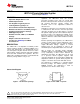
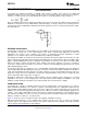
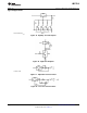
In operation, the LM317L-N develops a nominal 1.25V reference voltage, V
REF
, between the output and
adjustment terminal. The reference voltage is impressed across program resistor R1 and, since the voltage is
constant, a constant current I
1
then flows through the output set resistor R2, giving an output voltage of
(1)
Since the 100μA current from the adjustment terminal represents an error term, the LM317L-N was designed to
minimize I
ADJ
and make it very constant with line and load changes. To do this, all quiescent operating current is
returned to the output establishing a minimum load current requirement. If there is insufficient load on the output,
the output will rise.
EXTERNAL CAPACITORS
An input bypass capacitor is recommended in case the regulator is more than 6 inches away from the usual large
filter capacitor. A 0.1μF disc or 1μF solid tantalum on the input is suitable input bypassing for almost all
applications. The device is more sensitive to the absence of input bypassing when adjustment or output
capacitors are used, but the above values will eliminate the possibility of problems.
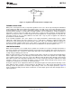
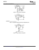
The adjustment terminal can be bypassed to ground on the LM317L-N to improve ripple rejection and noise. This
bypass capacitor prevents ripple and noise from being amplified as the output voltage is increased. With a 10μF
bypass capacitor 80dB ripple rejection is obtainable at any output level. Increases over 10μF do not appreciably
improve the ripple rejection at frequencies above 120Hz. If the bypass capacitor is used, it is sometimes
necessary to include protection diodes to prevent the capacitor from discharging through internal low current
paths and damaging the device.
In general, the best type of capacitors to use is solid tantalum. Solid tantalum capacitors have low impedance
even at high frequencies. Depending upon capacitor construction, it takes about 25μF in aluminum electrolytic to
equal 1μF solid tantalum at high frequencies. Ceramic capacitors are also good at high frequencies; but some
types have a large decrease in capacitance at frequencies around 0.5MHz. For this reason, a 0.01μF disc may
seem to work better than a 0.1μF disc as a bypass.
Although the LM317L-N is stable with no output capacitors, like any feedback circuit, certain values of external
capacitance can cause excessive ringing. This occurs with values between 500pF and 5000pF. A 1μF solid
tantalum (or 25μF aluminum electrolytic) on the output swamps this effect and insures stability.
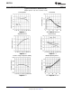
LOAD REGULATION
The LM317L-N is capable of providing extremely good load regulation but a few precautions are needed to
obtain maximum performance. The current set resistor connected between the adjustment terminal and the
output terminal (usually 240Ω) should be tied directly to the output of the regulator rather than near the load. This
eliminates line drops from appearing effectively in series with the reference and degrading regulation. For
example, a 15V regulator with 0.05Ω resistance between the regulator and load will have a load regulation due to
line resistance of 0.05Ω × I
L
. If the set resistor is connected near the load the effective line resistance will be
0.05Ω (1 + R2/R1) or in this case, 11.5 times worse.
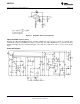
Figure 17 shows the effect of resistance between the regulator and 240Ω set resistor.
With the TO-92 package, it is easy to minimize the resistance from the case to the set resistor, by using two
separate leads to the output pin. The ground of R2 can be returned near the ground of the load to provide
remote ground sensing and improve load regulation.
6 Submit Documentation Feedback Copyright © 2000–2013, Texas Instruments Incorporated
Product Folder Links: LM317L-N