
Data Sheet

LM317L-N
www.ti.com
SNVS775J –MARCH 2000–REVISED MARCH 2013
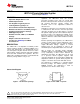
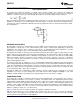
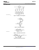
Figure 17. Regulator with Line Resistance in Output Lead
THERMAL REGULATION
When power is dissipated in an IC, a temperature gradient occurs across the IC chip affecting the individual IC
circuit components. With an IC regulator, this gradient can be especially severe since power dissipation is large.
Thermal regulation is the effect of these temperature gradients on output voltage (in percentage output change)
per watt of power change in a specified time. Thermal regulation error is independent of electrical regulation or
temperature coefficient, and occurs within 5ms to 50ms after a change in power dissipation. Thermal regulation
depends on IC layout as well as electrical design. The thermal regulation of a voltage regulator is defined as the
percentage change of V
OUT
, per watt, within the first 10ms after a step of power is applied. The LM317L-N
specification is 0.2%/W, maximum.
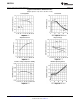
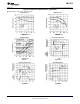
In the Thermal Regulation curve at the bottom of the Typical Performance Characteristics page, a typical
LM317L-N's output changes only 7mV (or 0.07% of V
OUT
= −10V) when a 1W pulse is applied for 10ms. This
performance is thus well inside the specification limit of 0.2%/W × 1W = 0.2% maximum. When the 1W pulse is
ended, the thermal regulation again shows a 7mV change as the gradients across the LM317L-N chip die out.
Note that the load regulation error of about 14mV (0.14%) is additional to the thermal regulation error.
PROTECTION DIODES
When external capacitors are used with any IC regulator it is sometimes necessary to add protection diodes to
prevent the capacitors from discharging through low current points into the regulator. Most 10μF capacitors have
low enough internal series resistance to deliver 20A spikes when shorted. Although the surge is short, there is
enough energy to damage parts of the IC.
When an output capacitor is connected to a regulator and the input is shorted, the output capacitor will discharge
into the output of the regulator. The discharge current depends on the value of the capacitor, the output voltage
of the regulator, and the rate of decrease of V
IN
. In the LM317L-N, this discharge path is through a large junction
that is able to sustain a 2A surge with no problem. This is not true of other types of positive regulators. For output
capacitors of 25 μF or less, the LM317L-N's ballast resistors and output structure limit the peak current to a low
enough level so that there is no need to use a protection diode.
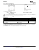
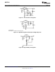
The bypass capacitor on the adjustment terminal can discharge through a low current junction. Discharge occurs
when either the input or output is shorted. Internal to the LM317L-N is a 50Ω resistor which limits the peak
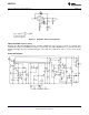
discharge current. No protection is needed for output voltages of 25V or less and 10μF capacitance. Figure 18
shows an LM317L-N with protection diodes included for use with outputs greater than 25V and high values of
output capacitance.
Copyright © 2000–2013, Texas Instruments Incorporated Submit Documentation Feedback 7
Product Folder Links: LM317L-N