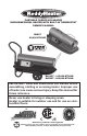
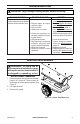
PORTABLE FORCED AIR HEATER KEROSENE/DIESEL HEATER WITH BUILT-IN THERMOSTAT OWNER’S MANUAL RH80T 80,000 BTU/HR RH145T - 145,000 BTU/HR RH220T - 200,000 BTU/HR IMPORTANT: Read and understand this manual before assembling, starting or servicing heater. Improper use of heater can cause serious injury. Keep this manual for future reference. Never use heater in living or sleeping areas. Heater is suitable for outdoor use and for use on combustible floors.
TABLE OF CONTENTS Safety......................................................... 2 Unpacking.................................................. 3 Assembly.................................................... 3 Product Identification and Label Locations.... 4 Specifications............................................. 5 Fuels........................................................... 5 Ventilation................................................... 5 Operation...................................................
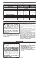
SAFETY 7. Minimum clearance from any combustible materials: 8 feet (244 cm) from hot air outlet, 6 feet (183 cm) from top, and 4 feet (120 cm) from sides and inlet. 8. Locate heater on a stable and level surface while hot or operating or a fire may occur. 9. Heater is acceptable for use on flooring such as wood (a combustible material). 10. Use only in well vented areas. Before using heater, provide at least a 3 ft 2 (2800 cm2) opening of fresh, outside air for each 100,000 Btu/Hr (30 kw) of rating. 11.
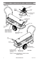
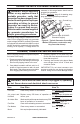
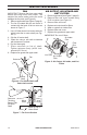
PRODUCT IDENTIFICATION AND LABEL LOCATIONS Right Side Cold Air Inlet Serial Number Label Power Cord Fueling Label 160168-01 Fuel Gauge Fuel Cap Caution Label 160172-01 Fuel Tank Thermostat Knob CSA/Control Label RH80T 200353-01 RH145T 200353-02 RH220T 200353-03 Maintenance Label 160175-01 Wire Guard Hot Air Outlet Warning Label 160195-01 Eng/Frn NY, MA and CA Information Label 160169-01 Warning Label 160110-03 Spn Left Side Figure 2 - Product Identification & Label Locations (RH220T Shown) 4 www
SPECIFICATIONS Output Rating Fuel Fuel Tank Capacity Fuel Consumption (per hr) Pump Pressure Electric Requirements Amperage (Normal Run) Typical Motor Speed Motor Shipping Weight Heater Weight without Fuel (approx) RH80T RH145T RH220T 80,000 Btu/Hr 145,000 Btu/Hr 220,000 Btu/Hr Use only kerosene, #1/#2 diesel*/fuel oil, JET A or JP-8 fuels 5.5 gal/20.8 L 10 gal/37.9 L 14 gal/53 L 0.60 gal/2.3 L 1.08 gal/4.1 L 1.64 gal/6.2 L 3.8 PSI (hot) 6.8 PSI (hot) 8.4 PSI (hot) 120 V/60 HZ 120 V/60 HZ 120 V/60 HZ 3.
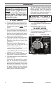
OPERATION IMPORTANT: Review and understand the warnings in the Safety section, pages 2 and 3. They are needed to safely operate this heater. Follow all local ordinances and codes when using this heater. TO START HEATER The LED will flash for 8 seconds before ignition. The LED will remain on during heater operation, even if the heater is cycled off by the thermostat. The LED will flash rapidly if the heater shuts down for any reason (Example: If out of fuel).
OPERATION WITH PORTABLE GENERATOR WARNING: Before operating heater or any appliance from a portable generator, verify that generator has been properly connected to earth ground. Improper grounding or failure to ground generator can result in electrocution if a ground fault occurs. Refer to owner’s manual supplied by generator manufacturer for proper grounding procedures. Operating voltage range of heater is 95 to 135 Volts.
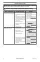
TROUBLESHOOTING WARNING: Never service heater while it is plugged in, operating or hot. Severe burns and electrical shock can occur. WARNING: High voltage! Unplug heater before servicing. FAULT CONDITION POSSIBLE CAUSE Motor does not start eight sec- 1. No power to heater. onds after heater is plugged in. 2. Thermostat setting is too low. 3. Bad electrical connection between motor and ignition control assembly or ignition control assembly and power cord. 4. Binding pump rotor. 5.
TROUBLESHOOTING WARNING: High voltage! Unplug heater before servicing. FAULT CONDITION POSSIBLE CAUSE REMEDY Heater ignites but ignition 1. Pump pressure incorrect. control assembly shuts heater off after a short period of time. 2. Dirty air intake, air output, and/or lint filter. 3. Dirty fuel filter. 4. Obstruction in nozzle. 1. See Pump Pressure Adjustment, page 11. 2. See Air Output, Air Intake, and Lint Filters, page 10. 3. See Fuel Filter, page 11. 4. See Nozzle Assembly, page 13. 5.
SERVICE PROCEDURES FAN IMPORTANT: Remove fan from motor shaft before removing motor from heater. The weight of the motor resting on the fan could damage the fan pitch (see Figure 6). 1. Remove upper shell (see Figure 5, page 9). 2. The fan is located with the set screw in contact with the back of flat on motor as shown in Figure 7. 3. Use 1/8" Allen wrench to loosen setscrew which holds fan to motor shaft (see Figure 6). 4. Slip fan off motor shaft. 5.
SERVICE PROCEDURES FUEL FILTER PUMP PRESSURE ADJUSTMENT 1. Remove pressure gauge plug from filter end cover (see Figure 9). 2. Install 0-15 PSI pressure gauge. 3. Start heater (see Operation, page 6). Allow heater to reach operating temperature (approx. 10 minutes). 4. Adjust pressure. Turn relief valve to right to increase pressure. Turn relief valve to left to decrease pressure. See specifications in Figure 10 for correct pressure. 5. Remove pressure gauge.
SERVICE PROCEDURES IGNITOR 1. Remove upper shell and fan guard (See Upper Shell Removal, page 9. 2. Remove fan (see page 10). 3. Remove the control side cover with a 5/16" nut driver. Remove side cover (see Figure 12). 4. Disconnect ignitor wires from ignition control assembly (see Figure 12). Pull the ignitor wires up through the hole in the lower shell. 5. Disconnect fuel line hose and air line hose. Remove photocell from photocell bracket (see Figure 12). 6. Remove combustion chamber.
SERVICE PROCEDURES NOZZLE ASSEMBLY 1. Remove upper shell (see Upper Shell Removal, page 9). 2. Remove fan (see Fan, page 10). 3. Remove fuel and air line hoses from nozzle assembly (see Figure 14). 4. Turn nozzle assembly 1/4 turn to left and pull toward motor to remove (see Figure 15). 5. Place plastic hex-body into vise and lightly tighten. 6. Carefully remove nozzle from the nozzle adapter using 5/8" socket wrench (see Figure 16). 7. Blow compressed air through face of nozzle.
SERVICE PROCEDURES PUMP ROTOR Blade (Procedure if Rotor is Binding) 1. Remove upper shell (see Upper Shell Removal, page 9). 2. Remove filter end cover screws using 5/16" nut driver (see Figure 17). 3. Remove filter end cover and air filters. 4. Remove pump plate screws using 5/16" nut-driver. 5. Remove pump plate. 6. Remove rotor, insert, and blades (see Figure 18). 7. Check for debris in pump. If debris is found, blow out with compressed air. 8. Install insert and rotor. 9.
WIRING DIAGRAM Photocell Photocell Heater Control Assembly Photocell Temp Thermostat Control Temp Green to Shell Motor Ignitor RET White Motor Neutral (N) White 120V (L1) Black Motor Red Red Green Power Plug 120V/60Hz Ignitor Ignitor TECHNICAL SERVICE You may have further questions about installation, operation, or troubleshooting. If so, contact SHM International, Corp. at 1-800-229-5647. When calling, please have your model and serial numbers of your heater ready.
PARTS MODELS RH80T, RH145T & RH220T 1 32 18 33 2 3 20 4 21 9 5 7 6 8 15 34 30 16 31 17 10 11 19 22 17 23 12 24 13 14 25 26 29 27 28 16 www.sureheat.
PARTS MODELS RH80T, RH145T & RH220T This list contains replaceable parts used in your heater. When ordering parts, be sure to provide correct model and serial numbers (from model plate), and part number and description of desired part.
PARTS MOTOR AND PUMP ASSEMBLY MODELS RH80T, RH145T & RH220T 2 3 4 5 6 7 8 9 10 1 18 16 15 19 17 11 14 12 13 ITEM 1 2 3 4 5 6 7 8 9 10 11 12 13 14 15 16 17 18 19 18 PART # 160001-01 160023-01 160003-02 160006-01 160088-01 160007-01 160009-01 160008-01 160010-01 160057-01 160025-01 160024-01 160090-01 160089-01 160029-01 160004-01 160052-01 160053-01 160189-01 DESCRIPTION Motor Rotor Insert Pump Rotor Pump Body Screw, 10-32 x .
PARTS PHOTOCELL ASSEMBLY MODELS RH80T, RH145T & RH220T 2 ITEM PART # DESCRIPTION 1 160041-03 Photocell Bracket 2 160092-02 Screw, 6-32 x .
PARTS WHEEL AND HANDLES MODELS RH145T & RH220T 1 3 5 4 6 7 2 9 8 ITEM 1 2 3 4 5 6 7 8 9 20 PART # 160074-01 160079-01 160072-01 160158-01 160072-12 160072-13 160129-01 160080-01 160130-01 DESCRIPTION QTY Rear Handle 1 Axle 1 Wheel Support Frame 2 Support Bushing 2 Fuel Tank Support Assembly 1 Screw, M10-1.5 x 60 2 Acorn Nut 2 Wheel 2 Wheel Spacer 2 www.sureheat.
REPLACEMENT PARTS Note: Use only original replacement parts. This will protect your warranty coverage for parts replaced under warranty. PARTS UNDER WARRANTY PARTS NOT UNDER WARRANTY Call Customer Service toll free at 1-800-229-5647 to order parts under warranty.
WARRANTY KEEP THIS WARRANTY Model ________________________________ Serial No. _____________________________ Date Purchased ________________________ Keep receipt for warranty verification. IMPORTANT: We urge you to fill out your warranty information above. Complete with the entire serial number which can be found on the rating plate. Retain this manual for future reference. Always specify model and serial numbers when communicating with customer service.
CALENTADOR PORTÁTILES DE AIRE FORZADO CALENTADOR DE KEROSENO/DIESEL CON TERMOSTATO INCORPORADO MANUAL DEL PROPIETARIO RH80T 80,000 BTU/H RH145T - 145,000 BTU/H RH220T - 200,000 BTU/H IMPORTANTE: Lea y comprenda este manual antes de ensamblar, encender o dar servicio al calentador. El uso inadecuado del calentador puede causar lesiones graves. Conserve este manual para referencias futuras. Nunca utilice el calentador en dormitorios o salas de estar y para el uso en combustible pisos.
TABLA DE CONTENIDOS Seguridad................................................. 24 Desempaque............................................ 26 Ensamble................................................. 26 Especificaciones ...................................... 26 Identificación del producto y ubicación de la etiqueta...................... 27 Combustibles............................................ 28 Ventilación................................................ 28 Funcionamiento...................................
SEGURIDAD combustible integrado al calentador o todo tanque auxiliar autorizado que esté conectado al equipo). g) De ser posible, el combustible debe almacenarse en áreas en las que la penetración del suelo no permita que se filtre o se encienda a causa de un fuego proveniente de un lugar menos elevado. h) El almacenamiento de combustible debe cumplir con las disposiciones de la autoridad competente. 3.
DESEMPAQUE 1. Saque todos los materiales en los que se empacó el calentador para el envío. 2. Saque todas las piezas de la caja. 3. Revise el calentador para ver si hay algún daño debido al transporte. Si el calentador está dañado, llame a SHM International Corp. al 1-800-229-5647 para obtener piezas de repuesto antes de devolverlo al distribuidor.
IDENTIFICACIÓN DEL PRODUCTO Y UBICACIÓN DE LA ETIQUETA Lateral derecho Aire frío entrada Cable eléctrico Número de serie Llenado de Combustible Etiqueta 160168-01 Combustible tapa Indicator de combustible Atención Etiqueta 160172-01 Tanque de combustible Perilla del termostato Etiqueta para el Control RH80T 200353-01 RH145T 200353-02 RH220T 200353-03 Mantenimiento Etiqueta 160175-01 Alambre guardia Aire caliente salida Nueva York, MA y CA Información de la Etiqueta 160169-01 Advertencias en la Etiq
COMBUSTIBLES ADVERTENCIA: Utilice sólo keroseno, diesel/aceite combustible Nº 1 ó Nº 2, o bien combustible de aviación JET A o JP-8 para evitar el riesgo de incendio o explosión. Nunca utilice gasolina, aceite usado de cárter, nafta, disolventes de pintura, alcohol u otros combustibles altamente inflamables. Utilice sólo keroseno, diesel*/aceite combustible Nº 1/Nº 2, o bien combustible de aviación JET A o JP-8.
FUNCIONAMIENTO Si la temperatura del termostato conjunto es más alta que la temperatura del aire circundante, el calentador debe encender inmediatamente. Si el termostato del calentador de la temperatura es más baja que rodea la temperatura del aire, el calentador no se enciende. La exposición a la luz solar directa o frío extremo puede afectar la lectura de temperatura y / o el funcionamiento del termostato. El LED parpadea durante 8 segundos antes ignición.
FUNCIONAMIENTO CON GENERADOR PORTÁTIL ADVERTENCIA: Antes de utilizar el calentador o cualquier dispositivo de un generador portátil, verifique que el generador se encuentre correctamente conectado a tierra. La falta de una conexión a tierra o la existencia de una conexión defectuosa pueden ocasionar una electrocución ante una falla. Consulte el manual del propietario suministrado por el fabricante del generador para obtener información sobre los procedimientos de conexión a tierra correctos.
PROGRAMA DE MANTENIMIENTO PREVENTIVO ADVERTENCIA: No repare el calentador mientras está enchufado, en funcionamiento o caliente. Pueden ocurrir quemaduras graves y electrocución. Artículo Frecuencia Método Tanque de com- Limpie en cada estación o según sea Consulte la sección Almacebustible necesario. namiento, transporte y envío, página 30. Filtros de salida de Reemplace cada 500 horas de uso o una Consulte Filtros de salida aire y partículas vez al año. de aire, entrada de aire y de pelusa, página 34.
SOLUCIÓN DE PROBLEMAS ADVERTENCIA: Alta tensión! Desenchufar calentador antes de dar servicio. CONDICIÓN DE FALLA POSIBLE CAUSA El motor se enciende y fun- 1. No hay combustible en el ciona pero el calentador no tanque. enciende. 2. La presión de la bomba no es la correcta. 3. El filtro de combustible está sucio. 4. La boquilla está obstruida. 5. Hay agua en el tanque de combustible. El calentador se enciende pero el ensamblaje del control de encendido lo apaga después de unos pocos minutos.
PROCEDIMIENTOS DE SERVICIO ADVERTENCIA: Para evitar el riesgo de sufrir quemaduras o electrocución, nunca intente reparar el calentador mientras está enchufado, en funcionamiento o caliente. DESMONTAJE DE LA CUBIERTA SUPERIOR 1. Retire los 8 tornillos ubicados a lo largo del calentador con un destornillador para tuercas de 5/16". Estos tornillos mantienen unidas la cubierta superior y la inferior (consulte la figura 5). 2. Levante y retire la cubierta superior. 3. Retire el protector del ventilador.
PROCEDIMIENTOS DE SERVICIO FILTROS DE SALIDA DE AIRE, ENTRADA DE AIRE Y DE PELUSA 1. Desmonte la cubierta superior (consulte las figura 5, página 31). 2. Extraiga los tornillos de la cubierta del extremo del filtro con un destornillador para tuercas de 5/16" (consulte la figura 8). 3. Desmonte la cubierta del extremo del filtro. 4. Reemplace los filtros de salida de aire y de pelusa. 5. Lave o reemplace el filtro de entrada de aire. 6. Vuelva a colocar la cubierta del extremo del filtro. 7.
PROCEDIMIENTOS DE SERVICIO FILTRO DE COMBUSTIBLE ENCENDEDOR 1. Quite los tornillos de la cubierta lateral utilizando un destornillador para tuercas de 5/16". 2. Quite la tapa lateral. 3. Quite la línea superior de combustible del cuello del filtro de combustible (consulte las figura 11). 4. Saque cuidadosamente el buje, el filtro de combustible y la línea inferior de combustible del tanque de combustible (consulte la figura 11). 5.
PROCEDIMIENTOS DE SERVICIO 7. Desmonte el tornillo del encendedor con un destornillador para tuercas de 1/4". Desmonte cuidadosamente el encendedor del soporte adaptador de la boquilla. PRECAUCIÓN: No doble ni golpee el elemento encendedor. Manéjelo con cuidado. 8. Saque cuidadosamente el encendedor de repuesto del empaque de espuma de estireno. 9. Guíe cuidadosamente el encendedor hacia dentro de la abertura en el soporte adaptador de la boquilla. No golpee el elemento encendedor.
PROCEDIMIENTOS DE SERVICIO 10. Fije el ensamblaje de la boquilla al soporte del quemador (consulte la figura 15). 11. Conecte las mangueras de las líneas de aire y combustible al ensamblaje de la boquilla. 12. Vuelva a colocar el ventilador (consulte Ventilador, página 33). 13. Vuelva a colocar el resguardo del ventilador y la cubierta superior (consulte Desmontaje de la cubierta superior, página 33).
PROCEDIMIENTOS DE SERVICIO 13. Realice los pasos 1 a 6. ROTOR DE LA BOMBA 14. Coloque un pedazo de lija muy fina (de (Procedimiento en caso que el grano 600) en una superficie plana. Lije el rotor esté atascado) rotor ligeramente haciendo movimientos 1. Desmonte la cubierta superior (consulte en forma de “8” cuatro veces (consulte la Desmontaje de la cubierta superior, páfigura 19). gina 33). 2. Quite los tornillos de la cubierta del extremo 15. Vuelva a instalar la parte de inserción y el rotor.
DIAGRAMA DE CABLEADO Asamblea control del calentador Fotocélula Fotocélula Fotocélula Temperatura Control de termostato Temperatura Motor Encendedor RET Motor Blanco Neutral (N) Blanco 120V (L1) Negro Motor Rojo Verde que desembolsar Verde Enchufe eléctrico 120V/60Hz Rojo Encendedor Encendedor SERVICIO TÉCNICO Es posible que tenga preguntas adicionales sobre la instalación, el funcionamiento o la solución de problemas. De ser así, póngase en contacto con SHM International, Corp.
PIEZAS MODELOS RH80T, RH145T Y RH220T 1 32 18 33 2 3 20 4 21 9 5 7 6 8 15 34 30 16 31 17 10 11 19 22 17 23 12 24 13 14 25 26 29 27 28 40 www.sureheat.
PIEZAS MODELOS RH80T, RH145T Y RH220T Esta lista contiene las partes reemplazables utilizadas en el calentador. Al ordenar las partes, asegúrese de proporcionar el número de modelo y número de serie correctos (de la placa del modelo), después el número de parte y descripción de la parte deseada. Art. 1 2 3 4 5 6 7 8 9 10 11 12 13 14 15 16 17 18 19 20 21 22 23 24 25 26 27 28 29 30 31 32 33 34 RH80T RH145T RH220T 160075-01 ** ** ** 160075-02 ** ** ** 160075-03 ** ** ** Descripción Cant.
PIEZAS ENSAMBLAJE DEMOTOR Y BOMBA MODELOS RH80T, RH145T Y RH220T 2 3 4 5 6 7 8 9 10 1 18 16 15 19 17 11 14 12 13 Art. 1 2 3 4 5 6 7 8 9 10 11 12 13 14 15 16 17 18 19 42 Pieza # 160001-01 160023-01 160003-01 160006-01 160088-01 160007-01 160009-01 160008-01 160010-01 160057-01 160025-01 160024-01 160090-01 160089-01 160029-01 160004-01 160052-01 160053-01 160189-01 Descripción Motor Insertar Rotor Bomba de Rotor Bomba de Anillo Tornillo, 10-32 x .
PIEZAS ENSAMBLAJE DE LA FOTOCÉLULA MODELOS RH80T, RH145T Y RH220T 2 Art. 1 2 3 3 Pieza # Descripción Cant. 160041-03 Soporte de la Fotocélula 1 160092-02 Tornillo, 6-32 x .38 2 160016-01 Montaje de Fotocélula 1 1 BOQUILLA ASAMBLEA MODELS RH80T & RH145T MODEL RH220T 7 4 11 5 2 7 2 11 9 9 10 3 Art.
PIEZAS RUEDAS Y MANIJA MODELOS RH145T Y RH220T 1 3 5 4 6 7 2 9 8 Art. 1 2 3 4 5 6 7 8 9 44 Pieza # 160074-01 160079-01 160072-01 160158-01 160072-12 160072-13 160129-01 160080-01 160130-01 Descripcíon Trasero Manejar Eje Rueda Marco Cojinete Tanque de apoyo Tornillo, M10-1.5 x 60 Tuerca Rueda Espaciador www.sureheat.com Cant.
PIEZAS DE REPUESTO Nota: use sólo piezas de repuesto originales. Esto protegerá la cobertura de su garantía para partes remplazadas bajo la garantía. PIEZAS CON Llame al número de servicio al cliente al 1-800-229-5647 para solicitar piezas en garantía.
NOTES ________________________________________________________________ ________________________________________________________________ ________________________________________________________________ ________________________________________________________________ ________________________________________________________________ ________________________________________________________________ ________________________________________________________________ ___________________________________________________
NOTES ________________________________________________________________ ________________________________________________________________ ________________________________________________________________ ________________________________________________________________ ________________________________________________________________ ________________________________________________________________ ________________________________________________________________ ___________________________________________________
GARANTÍA GUARDE ESTA GARANTÍA Modelo___________________________________ Número de serie___________________________ Fecha de compra __________________________ Conserve su recibo para la verificación de la garantía. IMPORTANTE: Le pedimos que complete la información de su garantía antes mencionada. Completo con todo el número de serie que se puede encontrar en la placa de características. Conserve este manual para futuras consultas.