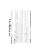
NOTE: Any photos of the YBIKE or decals in the owner’s manual are intended to be used as a reference only, and there may be some differences to the unit you purchased.
WARNING! CHOKING HAZARD—Small parts. Injury may occur if these precautions are not observed. x Children riding the bicycle should have constant adult supervision. A responsible adult must inspect the bicycle prior to use, to ensure that all parts are fully assembled and tightened to prevent accidents. x Always wear proper protective gear such as a helmet, elbow and kneepads as well as appropriate clothing such as a long sleeve shirt, gloves, long pants and closed footwear.
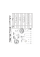
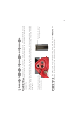
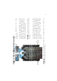
NAME BRACKET BOLTS X2 (PRE-ASSEMBLED) HANDLEBAR (WITH WHEEL) MAIN FRAME HANDLE STEERING CAPS X2 WHEELS X2 PEDALS X2 FLAT HEAD BOLTS X2 ROUND HEAD BOLTS X3 HANDLEBAR BOLT TRICYCLE: REAR WHEEL BOLT X2 BALANCE BIKE: REAR WHEEL BOLT RUNNING BIKE: REAR WHEEL BOLT TWO SETS OF ALLEN KEYS SEAT No.
2 Seat post 2 3 3 8 1 Place the front of the frame (No. 2) with handle steering caps (No.3) on top and underneath the frame, as in the picture above, and place this into the space provided on the handlebar (No. 1). Use the Allen keys (No.12) to secure into position with the flat bolt head (No.6) from below and handlebar bolt (No. 8) at the top, as in the picture above. Loosen the seat clamp. Insert the 6 seat post (No. 13) into the frame (No.
2 Balance Trike 3 Balance Bike 1 3 2 2 3 Swing Arms 1 Swing Arm Bracket 1 3 Holes for assembly on Swing Arm 2 Important Note 1: Each biking option is assembled using numbered holes on the swing arm bracket to correspond with the numbered holes on the swing arms. 1 Tricycle Your bike is now ready to be assembled into one of three great biking options. Please choose the corresponding assembly instruction in the pages that follow. 2.
Bolts 0, 9, 10 and 11 have square necks. Important Note 3: The pedals are only intended to be used with the tricycle. Remove the pedals during assembly for the Balance Trike or Balance Bike biking options. The square holes on the swing arm bracket and on both swing arms. These bolts must be inserted from the correct side, as shown in the corresponding assembly instruction. These square holes will keep the bolt from turning when securing it in place with the Allen keys.
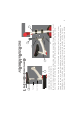
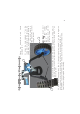
2.2 Place the wheel (No. 4)_on the outside edge of the swing arm, so that the wheel axel hole aligns perfectly with the hole marked “1” on the swing arm. DO NOT insert bolt (No. 0) from underneath the swing bracket, as it will not fit from this side. 7 2.1 Align the hole marked “1” on the swing arm bracket with the hole on the swing arm. Insert the bracket bolt (No. 0) from the seat side, and secure in place with a flat head bolt (No. 6) from underneath the swing bracket.
Pedal shaft Wheel Axel Hole Button Lever Turning mechanism Remove the pedals during assembly for the Balance Trike or Balance Bike biking options. Important: The pedals are only intended to be used with the tricycle.
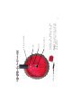
B Lever A Button Pedal shaft Wheel Axel Hole To remove the pedals: Press the button in, then slide the lever back to release the pedal shaft. 2.6 Release the lever. WARNING! The pedals can fit only one way. DO NOT force the pedals into the hole, but slowly rotate the hexagonal pedal shaft until it smoothly slides into the hexagonal wheel axel holes. 2.5 Now, while still holding the lever, gently slide the pedal shaft (No.
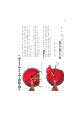
3.2 Place both wheels (No. 4) on the inside edge of the swing arms, so that the wheel axel holes align perfectly with the holes marked “2” on the swing arms. Now insert the wheel bolt (No. 10) and secure in place with flat head bolt (No. 7) using the Allen Keys (No.12). DO NOT insert bolt 0 from underneath the swing bracket, as it will not fit from this side. 3.1 Align the hole marked “2” on the swing arm bracket with the hole on the swing arm. Insert the bracket bolt (No.
4.2 Place one wheel (No. 4) on the inside edge of the swing arm, so that the wheel axel holes align perfectly with the holes marked “3” on the swing arms. Now insert the wheel bolt (No. 11) and secure in place with round head bolt (No.7) using the Allen Keys (No. 12). DO NOT insert bolt (No. 0) from underneath the swing bracket, as it will not fit from this side. 4.1 Align the hole marked “3” on the swing arm bracket with the hole on the swing arm. Insert the bracket bolt (No.
Check that all the bolts are tightened. Check that the handlebar is securely fastened and that it moves smoothly. Check that the wheels can spin smoothly and each part is securely fixed. Finally after checking the above points, you can now start to ride. WWW.YBIKEUSA.COM designed by www.chromecherry.com WWW.YBIKE.CO.ZA WARNING! This product must be assembled by an adult. Read the manufacturer’s instructions before using. Keep the instructions safe for future reference. 1. 2. 3. 4.