GB USE AND MAINTENANCE MANUAL MISTBLOWERS MOUNTED MISTBLOWERS serie EOLO - SIRIO - DEVIL - EXPO - AP APC Read this manual carefully before use.
Summary 1 USING AND KEEPING THE USE AND MAINTENANCE MANUAL .................... 4 1.1 1.2 1.3 1.4 COMPOSITION OF THE MANUAL ....................................................................................... GUARANTEE ....................................................................................................................... PRODUCT RESPONSIBILITY .............................................................................................. WARNING SIGNS IN THE MANUAL AND ON THE MACHINE ..
6.2.3 6.3 6.4 6.4.1 6.4.2 ANTI-DRIFT NOZZLES ....................................................................................................... 19 CALIBRATING AXIAL FAN ATOMISERS ............................................................................. 20 CALIBRATING CANNON ATOMISERS ................................................................................ 20 TREATMENTS ON TALL PLANTS .......................................................................................
Thank you for having chosen UNIGREEN. The product you purchased has been designed and built with the greatest attention to the safety of the operator and the environment, nevertheless there are still some residual risks due to the nature of the product used. For this reason we recommend reading all of this manual to avoid making mistakes in the first period of use and to get the most out of the working life of the atomiser in time, doing the programmed maintenance at regular intervals.
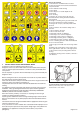
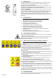
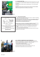
1 2 3 4 5 6 7 8 9 10 11 12 13 14 15 16 17 18 19 20 21 22 Key to the symbols 1- Read the Use and Maintenance manual 2- Stop the machine and read the manual before every intervention 3- Don’t lubricate while running 4- Don’t drink 5- Don’t dispose of residue liquids in the environment 6- No smoking 7- Danger, risk or injury, don’t get near the machine until the moving machine members have stopped 8- Danger of crushing, don’t get your hands near the moving mechanical machine members 9- Da
2.1 INTENDED USE The sprayer in this series is built for agricultural use. The materials used are resistant to normal chemical products used in agricultural spraying (or herbicides) at the time of construction. Any other use is not allowed and the manufacturer is not responsible for any damage caused by aggressive, dense or sticky chemicals.
Refer to the enclosed handbooks for the use and maintenance of the pump and pressure regulator and any accessories or motors. b) Please contact the agent in your zone, the nearest authorised workshop or UNIGREEN S.p.A. directly for any repairs the user feels they aren’t capable of performing alone. (see point 10.4) c) Due to the complexity of the equipment and the variety of technologies used (mechanical, hydraulic, oil-pressure and electrotechnical) operators must not dismantle or modify the equipment.
3.2 NOISE LEVEL OF THE MACHINE Use earmuffs to protect your ears when using the machine, below you will find the data on the maximum noise levels during work. Atomisers with axial fan rotor ACOUSTIC POWER LEVEL emitted by the machine with axial fan rotor: 113.5 and 118.5 dBA respectively in 1st and 2nd gear ACOUSTIC POWER LEVEL AT THE OPERATOR’S POSITION emitted by the machine with axial fan rotor: 89.0 and 89.
When you receive the machine, check that it is complete and no parts are missing. If there are any damaged parts, inform your local reseller or UNIGREEN directly in good time. When the machine is delivered, make sure you ask: a) that the machine is delivered with all of its parts fitted and that the fitting meets the requisites in table N° 14b-15b-16b (pages 37, 38, 39). This procedure is necessary because for reasons of space during transportation the machine is often delivered partially dismantled.
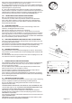
4.4 TRACTOR COUPLING The tractor must have 1”3/8 ASAE DIN 9611/A power-takeoff that runs at 550 rpm. It must have a 3-point elevator suitable for safely supporting the weight of the atomiser. Check this by consulting the table of allowed fittings N° 14A-15A-16A (pages 37, 38, 39). WARNING: make sure there are no persons or things near the atomiser before starting the machine and while you are using it. FIG. 4 Tractor coupling 4.4.
4.5 CARDAN SHAFT In some models this is supplied on request. The cardan shaft must bear the CE mark. It must always have its own instructions that must be followed scrupulously and it should come with a cover bearing the mark, integrated in every part. You should have previously checked the length to avoid: = if it is too long, DANGEROUS THRUST ON THE PUMP SHAFT = if too short, the POSSIBILITY OF DANGEROUS BREAKAGES FIG. 6 FIG.
Don’t use the sprayer without having consulted the enclosed handbook. way 4.8 PRESSURE REGULATOR To use the pressure regulator, follow the instructions in the enclosed handbook scrupulously. The pressure regulator controls all of the most important spraying functions, the thorough knowledge of its functions makes work easier and more precise.
Pressure regulators with a volumetric valve (GCP ELETTRICO) Adjusting the maximum pressure valve = put main control A in the drain position (“OFF”). = loosen the hand wheel of maximum pressure valve B completely (anticlockwise). = open volumetric valve E completely. = start the pump by activating the power-takeoff of the tractor at 540rpm = open main control A (position “ON”), the manometer will be activated = open the drain tap on filter F slightly (only GCP ELETTRICO).
FIG. 10 4.10 FILLING THE TANK The machines for defensive crop treatments, in consideration of the safety of persons, animals and the protection of the environment, must only be filled indirectly from open water courses and only by free-falling water from the waterworks. The pipe used for filling must never come into contact with the liquid inside the tank and therefore the water must always fall over the upper edge of the filling inlet and through the filter installed on it.
a) high-pressure machines from 30 to 60 bar (FIG. N° 13): run the stirrer (or ejector) for roughly 10-15 minutes at the maximum pressure available FIG. 13 FIG. 14 b) low pressure machines, max 20 bar = with a drilled pipe on the drain, run the pump at roughly 540 RPM with the pressure regulator on drain for at least 10-15 minutes. (FIG. N° 14) = with the stirrer on a delivery, run the pump supplying the stirrer (or ejector) at the maximum pressure available for at least 10-15 minutes. (FIG.
5 BLOWER GROUP All the atomisers have a high speed fan rotor. You must take great care and beware of the effects that this can provoke: such as the aspiration and projection of foreign bodies which, although of a small size, can be very dangerous especially for the eyes and face. Belt tensioning system FIG. 17 5.1 AXIAL BLOWER GROUP WITH PULLEY The atomisers that have a drive transmission between the pump and fan with pulleys are equipped with a neutral gear; the multiplied ratio is 1:4.
WORK TEMPERATURE Heat is generated by the friction between the various moving components and on the basis of the power transmitted. The temperature of the multiplier or disengaging box depends on the capacity to dissipate heat to the surrounding environment and therefore the surfaces involved in the heat exchange and the environmental conditions. The specifications refer to environmental conditions with a temperature between -10° +50°C (14°C -122°F).
FIG. 23 FIG. 24 5.5 CLUTCH Big aluminium and nylon blowers have a centrifugal type clutch that makes it possible to engage the fan rotor gradually. This prevents jerky starts, due to the inertia of the fan rotor, which can have a negative effect on the transmission. For the centrifugal clutch to work properly the speed of the power-takeoff mustn’t be less than 450 rpm, especially if you are using the first gear of the multiplier.
To prevent the excessive heating of the oil we recommend supplying the distributor of the sprayer only when the cylinders are being used. We recommend having qualified personnel do any adjustments. Pay attention to the integrity and efficiency of the hydraulic components and in particular to the pipes to prevent the risk of bursting. Do a full check on the pipes and components at least once a year, we recommend replacing hydraulic pipes every 3-4 years. 6 SPRAYING 6.
6.3 NB: for calculating a different space between rows simply multiply the litres/hectare value by the corresponding width indicated in the table and divide it by the new width.
6.4.2 TREATMENTS ON HERBACEOUS CULTIVATIONS a) Use the tables of pages 31-33 choosing the one relevant to the type of cannon to use and the number of jets. b) Find the range and the diameter of the nozzles used (ceramic plate or TR nozzles). c) In the horizontal strip, choose the working speed and the distribution in litres/hectare and on the vertical scale find the pressure to use. d) Adjust the pressure to obtain the treatment required.
8 MAINTENANCE All of the maintenance operations and repairs must be carried out with the machine and cardan shaft stopped and the tank and circuit clean of any residues of chemical products. The maintenance of the atomiser is essential for maintaining a high level of safety. Also consult the single handbooks of the main components of the atomiser. 8.1 PROGRAMMED MAINTENANCE (TAB.
We recommend having the normal UNIGREEN assistance service available from our reseller perform any repairs or contact a specialised workshop. During all of the repairs, in particular when welding, the machine and the circuit must be clean of any residues of chemical product. If the machine has to be lifted (for example to change a wheel) follow the instructions in point 4.3 of the present handbook.
d) reducing the use of dangerous substances in electrical and electronic apparatus. The decree imposes the limitation and elimination of several substances present in EEAW: lead, mercury, cadmium, chrome, hexavalent chrome, polybrominated biphenyl, polybrominated diphenyl and polybrominated diphenyl ethers. The machine has been designed and created in conformity with this directive. Follow the indications shown below.
TABLES FOR CALIBRATING ATOMISERS TABLES FOR CALIBRATING ATOMISERS Ø500-600 unigreen spa Tabella erogazione in Litri/ettaro Gr.Ventola Ø500-Ø600 8 getti Lt.
TABLES FOR CALIBRATING ATOMISERS TABLES FOR CALIBRATING ATOMISERS Ø600-650 unigreen spa Tabella erogazione in Litri/ettaro Gr.Ventola Ø600-Ø650 10 getti Lt.
TABLES FOR CALIBRATING ATOMISERS TABLES FOR CALIBRATING ATOMISERS Ø700-750 unigreen spa Tabella erogazione in Litri/ettaro Gr.Ventola Ø700-Ø750 12 getti Lt.
TABLES FOR CALIBRATING ATOMISERS TABLES FOR CALIBRATING ATOMISERS Ø800 unigreen spa Tabella erogazione in Litri/ettaro Gr.Ventola Ø800 14 getti Lt.
TABLES FOR CALIBRATING ATOMISERS TABLES FOR CALIBRATING ATOMISERS Ø900 unigreen spa Tabella erogazione in Litri/ettaro Gr.Ventola Ø900 16 getti Lt.
TABLES FOR CALIBRATING ATOMISERS TABLES FOR CALIBRATING ATOMISERS Ø650 TGZ unigreen spa Tabella erogazione in Litri/ettaro Gr.Ventola Ø650 14 getti 14 GETTI Lt.
TABLES FOR CALIBRATING CANNONS TABLES FOR CALIBRATING CANNONS Ø450 unigreen spa Tabella erogazione in Litri/ettaro Cannone Ø450 2 getti Lt.
TABLES FOR CALIBRATING CANNONS TABLES FOR CALIBRATING CANNONS Ø400-455 unigreen spa Tabella erogazione in Litri/ettaro Cannone Ø400 6 getti + 2 laterali Lt.
TABLES FOR CALIBRATING CANNONS TABLES FOR CALIBRATING CANNONS Ø400-455 TILTING HEAD unigreen spa Tabella erogazione in Litri/ettaro Cannone Ø400 6 getti Testa Snodata Lt.
TABLE 1-3 TABLES OF DELIVERY OF NOZZLES FOR ATOMISERS TABLE OF DELIVERY IN LITRES / MIN. MEDIUM AND HIGH VOLUME Ø18 CONICAL NOZZLES FOR ATOMISER Ø NOZZLE Ø SLINGER PRESSURE TABLE.
TABLE 4-5 TABLES OF DELIVERY OF NOZZLES FOR HAND LANCES TABLE OF DELIVERY IN LITRES / MIN. OF THE CONICAL NOZZLES FOR LEVER LANCE note: standard Ø1,5 nozzle DIAMETER NOZZLE PRESSURE (BAR) TABLE.
TABLE 7 TABLE OF PROGRAMMED MAINTENANCE OPERATION 8h Check the level and state of the oil Check the accumulator pressure Check the suction (hoses, pipes, unions) Check and clean the suction and delivery filters Check the pump fixing feet and screws in general Check the diaphragm and the oil and change if necessary Check the suction/delivery valves Check the pump screws and bolts are tight Check and clean the nozzles and the non-drip diaphragm Check the wear of the nozzles Check the hydraulic oil level C
TAB.14A ALLOWED FITTINGS 2007 ATOMIZZATORI PORTATI TYPE OF PLT MACHINE Truck-mounted mistblowers TAB.
TAB.15A ALLOWED FITTINGS 2007 TAB.
TAB.16A ALLOWED FITTINGS 2007 ATOMIZZATORI PORTATI A CANNONE TYPE OF Tractor-mounted mistblowers "Cannon Type" MACHINE TAB. 16 a EOLO C - SIRIO C APC BORA - APC APC FITTING FAN GROUP PUMPS COMET PUMPS ANNOVI REVERBERI PRESSURE REGULATOR JETS NOZZLES TOTAL MASS in Kg P HP Nominal capacity (lt.
Tel. +39 0522 369811 Fax. +39 0522 369898 e-mail: info@unigreen-spa.com internet: www.unigreen-spa.com member of the group Descriptions, indicative illustrations, UNIGREEN S.P.A. reserves the right to make variations or modifications without prior warning. UNI 16100005F - GB Gen-07 via Rinaldi, 105 - Loc.