
Data Sheet
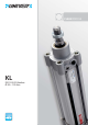

KL
4
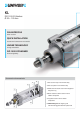
- New design of the pro le for easier cleaning
- Grooves for recessed sensors and connections on one side
for easy installation
- Traditional UNIVER technology to ensure strength and reliability
- Dimensions complying with international standards
for a full interchangeability
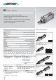
die-cast in aluminium alloy
pro led and anodized aluminium
die-cast in aluminium alloy
acetalic resin
chromium-plated steel standard, stainless steel upon request
lip seal in nitrilic resin
UNIVER Original self-lubricating and self-aligning
nitrilic rubber
standard supplied
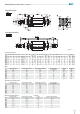
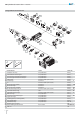
CONSTRUCTIVE CHARACTERISTICS
End caps
Barrel
Piston
Guide slide
Piston Rod
Piston Seal
Guide bush for rod
Cushion seals
Magnet
TECHNICAL CHARACTERISTICS
-20 ÷ 80 °C
ltered air with or without lubrication
1,5 ÷10 bar
Ø 32 - 40 - 50 - 63 - 80 - 100 - 125 mm
pneumatic and adjustable on both sides
Ambient temperature
Fluid
Working pressure
Bores
Cushionings
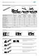
1
Series
3
Version
00 = D.A. Standard
01 = D.A. Through rod
40 = D.A. Reinforced bushing
60 = S.A. Retracted rod
Max stroke 50 mm
70 = S.A. Extended rod
Max stroke 50 mm
90 = D.A. High temperature seals
+120 °C
4
Bore
032 = Ø32
040 = Ø40
050 = Ø50
063 = Ø63
5
Stroke (mm)
= Preset for locking unit - reduced protrusion
= Preset for locking unit - ISO protrusion
= Metallic rod scraper
KL = Pneumatic cylinders
ISO 15552 Ø 32 ÷ 125 mm
Standard Magnetic
0025 - 0050 - 0075 - 0080 - 0100 - 0125 - 0150 - 0160
0175 - 0200 - 0250 - 0300 - 0320 - 0350 - 0400 - 0450
0500 - 0600 - 0700 - 0800 - 0900 - 1000
CODIFICATION KEY
1
K
2000320050
6
3
45
M
L
D.A. = Double-acting S.A. = Single-acting
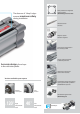
Opposed cylinders
Cylinders with common
piston rod
Cylinder with L1-N locking unit
Tandem cylinder
Two-position tandem cylinder
Further available versions
F
G
K
2
Type
1 = Stainless steel rod
2 = Chromium-plated
steel rod
2
7
= Magnetic version
(standard supplied)
M
080 = Ø80
100 = Ø100
125 = Ø125
6
Option
7
Magnetic
KL Ø 32 ÷ 125 mm