
Data Sheet

UNIVER GROUP
KL
7
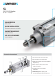
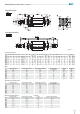
Magnetic sensor DF series
M12 versionM08 versionCable version
For version with connector M8 and M12 add M08 or M12 at the end of the part no.
Example: DF-770M08 or DF-770M12
Working voltage
Max switching current
Max switching power
Max voltage drop
Minimum magnetic eld
Opening response time
Closing response time
Electric life with resistive load
State indicator
Cable number and section
Electric circuit
Protection degree
Working temperature
V AC/DC
mA
W/VA
V AC/DC
gauss
ms
ms
cycles
LED
mmq
-
EN60529
°C
5÷30 V AC/DC
100
3
<3,5V
60
< 0,5
< 1
>10
7
red
2 x 0,14
A
5÷30 V AC/DC
100
3
0,1V
60
< 0,5
< 1
>10
7
red
3 x 0,14
C
5÷30 V DC
100
3
0,7V
30
0,08
0,03
>10
9
red
3 x 0,14
C
5÷30 V AC/DC
100
3
0,1V
60
< 0,5
< 1
>10
7
red
3 x 0,14
D
IP67
-20 ÷ +80 °C
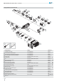
KL Cylinders ISO 15552 - Ø 32 ÷ 125 mm
3
2
1
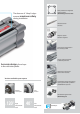
Assembly scheme
4
Put the sensor in the proper groove and make
sure that the fastening plate has the slot for screwdriver
along the sensor axis
Turn the sensor inside its groove and make sure that the
fastening plate is on the open part of the groove
Check the correct position of the sensor in the groove.
Turn it to the wished position for detection
Keep the sensor in its position and screw the fastening
plate to x the sensor in the groove
Max torque: 0,5 ÷ 1 Nm
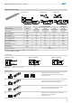
CA
D
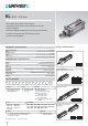
BRN = brown BLK = black BLU = blue
Electric circuits
AC/DC 2 wires NO DC 3 wires PNP NCDC 3 wires PNP NO
ELECTROMECHANICAL
ELECTRONIC
DF-330
3 wires PNP NO
CHARACTERISTICS TYPE
DF-220
2 wires NO
DF-440
3 wires PNP NC
DF-770
3 wires PNP NO