HIGH-RESOLUTION INTERFACE with Realtime UAD Processing Apollo FireWire Hardware Manual Manual Version 150421 Customer Service & Technical Support: +1-877-MY-UAUDIO (+1-877-698-2834) International: +1-831-440-1176 www.uaudio.
A Letter from Bill Putnam Jr. Thank you for deciding to make an Apollo High-Resolution Interface part of your music making experience. We know that any new piece of gear requires an investment of time and money — and our goal is to make your investment pay off. The fact that we get to play a part in your creative process is what makes our efforts meaningful, and we thank you for this.
Table Of Contents A Letter from Bill Putnam Jr. .................................................................................................................................ii Table Of Contents ................................................................................................................................................iii Introduction ...........................................................................................................................................
Introduction Apollo FireWire Audio Interface w/ QUAD Processing Apollo FireWire is one of the world’s most popular professional audio interfaces — delivering the sound, feel, and flow of analog recording to music creators everywhere. A perfect centerpiece for studios running original Mac Pro towers and Windows 7 machines, this 18 x 24 FireWire 800-equipped interface features analog design based on UA’s 50-year heritage, along with gold-standard Apollo A/D and D/A conversion for impeccable audio resolution.
Features Key Features • Worldwide standard in professional A/D and D/A conversion for music production • Onboard UAD-2 QUAD Core DSP allows Realtime UAD Processing — record through plug-ins from Neve, Lexicon, Studer, Marshall, Ampex, and more* • 4 Unison-enabled mic preamps for tracking through preamp emulations from Neve, API, and Universal Audio* • 18 x 24 FireWire audio interface for Mac and Windows 7 • Cascade two Apollos for 16 analog I/O channels and 12 digital I/O channels • Includes “Realtime Analo
UAD-2 Inside • QUAD Core DSP with four SHARC® processors • Realtime UAD Processing on all of Apollo’s analog and digital inputs • Same features and functionality as other UAD-2 devices when used with DAW • Can be combined with other UAD-2 devices for increased mixing DSP • Complete UAD Powered Plug-Ins library is available online Software Console application: • • • • • Analog-style mixer for realtime monitoring and tracking with UAD plug-ins Enables Realtime UAD Processing DSP mixer for realtime monitorin
About Apollo Documentation Documentation for all Apollo components is extensive, so instructions are separated by areas of functionality. Each functional area has a separate manual file. An overview of each file, and how they are accessed, is provided in this section. Note: Extensive documentation, including technical information not available in other publications, is also available online at: www.uaudio.com/support/apollo Apollo Manual Files Note: All manuals are in PDF format.
Installed Documentation Location All documentation is copied to the startup disk during software installation: Mac OS X • Macintosh HD/Applications/Universal Audio Windows 7 • Start>All Programs>UAD Powered Plug-Ins>Documentation Accessing Installed Documentation Any of these methods can be used to access installed documentation: • • • • Navigate the file system within the computer’s operating system Choose “Documentation” from the Help menu within the Console application Click the “View Documentatio
Technical Support Universal Audio provides free customer support to all registered Apollo users. Support specialists are available to assist you via email and telephone during normal business hours, which are from 9 AM to 5 PM, Monday through Friday, Pacific Standard Time. Email Support To request online support via email, click the link below for a direct link to the help ticket form: • www.uaudio.com/my/support/create Alternately, visit the main support page at www.uaudio.
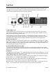
Front Panel This section describes the features and functionality of all controls and visual elements on the Apollo front panel. Note that all front panel functions, except the headphone volume knobs and power switch, can be controlled remotely with the included Console software application. (1) Hi-Z Inputs 1 & 2 The Hi-Z (high impedance) JFET direct inputs are for connecting low-level passive devices such as electric guitar and bass instruments into channels 1 & 2 for A/D conversion.
Channel Select Pushing the Preamp Knob changes the currently selected channel, which determines which input (1 – 4) is adjusted by the front panel preamp controls. A channel is selected for adjustment when its Channel Select Indicator LED (located above the channel 1 – 4 input meters; see #11 on page 12) is illuminated. Each time the knob is pushed, the selected preamp channel is incremented. If stereo linking is active, the stereo pairs are selected.
Only the same type of inputs can be linked (Mic/Mic or Line/Line). The Hi-Z inputs cannot be linked. (10) Preamp Options LEDs These seven LEDs display the state of the preamp option button settings for the currently selected channel. Each LED is illuminated when its associated option is active. When the channel selection is changed, the LED states are updated to reflect the current settings for the selected channel.
Front Panel (continued) (13) Power Indicator (UA Logo) The Universal Audio logo illuminates when the external power supply is properly connected to the AC outlet and the power input on the rear of the unit, and the Power switch (#22) is in the up position. Clock LEDs The Internal (“INT”) and External (“EXT”) Clock LEDs indicate the source and status of the system master clock. The clock source is specified within the Console application.
(17) Monitor Output Level Meters The 10-segment LED meters display the signal peak output levels for monitor outputs 1 & 2 (Left & Right) at the output of the D/A converters. These meters are before the Monitor Level control (pre-fader) and reflect the D/A converter levels regardless of the current Monitor Level and Headphone Level knob settings. The dB values of the monitor meter LEDs are indicated between the left and right channel meters. When digital clipping occurs, the red “CLIP” LED illuminates.
Rear Panel Analog I/O (1) Monitor Outputs 1 & 2 These balanced ¼” TRS phone jacks are line-level analog outputs typically used for connection to a stereo loudspeaker monitoring system. The signal levels at these outputs are controlled with the Monitor Level knob (#18). Unbalanced ¼” TS cables can also be used. The Monitor Outputs are completely independent from the eight Line Outputs. By default, the “1–2” or “Main” outputs from a DAW are routed to these outputs.
Digital I/O (5) Power Input The included external power supply plugs into this 4-pin locking XLR jack. To eliminate risk of circuit damage, connect only the factory-supplied power supply. Use the Power switch on the front panel to power the unit on and off. Important: Do not disconnect the power supply while Apollo is in use, and confirm the Power switch is in the “off” position before connecting or disconnecting the power supply.
The ADAT port channel assignments described above are summarized in this table: ADAT PORT CHANNEL ROUTING Sample Rate (kHz) Input Port 1 Input Port 2 Output Port 1 Output Port 2 44.1 & 48 1–8 Disabled 1–8 1 – 8 (mirror of port 1) 88.2 & 96 1–4 5–8 1–4 5–8 176.4 & 192 1–2 3–4 1–2 3–4 Note: The ADAT ports use TOSLINK JIS F05 optical connectors. Some devices use this type of connector for optical S/PDIF connections. However, Apollo’s ADAT ports do not support the S/PDIF protocol.
(10) 75 Ohm Word Clock Termination Switch This pushbutton switch provides internal 75-ohm word clock input signal termination when required. Word clock termination is active when the switch is engaged (depressed). Apollo’s termination switch should only be engaged when Apollo is set to sync to external word clock and it is the last device at the receiving end of a word clock cable.
Installation & Configuration Note: Items on this page are detailed in the Apollo Software Manual (see “About Apollo Documentation” on page 7). System Requirements All system requirements must be met for Apollo to operate properly. Before proceeding with installation, see the system requirements in the Apollo Software Manual. Software Installation The Apollo software must be installed to use Apollo and UAD plug-ins. The UAD Powered Plug-Ins software installer contains the Apollo software and drivers.
Interconnections Installation Notes • • Apollo may get hot during normal operation if it doesn’t receive adequate airflow circulation around its chassis vents. For optimum results when mounting Apollo in a rack, leaving at least one empty rack space above the unit to allow adequate airflow for cooling is recommended. As with any sound system, the following steps are recommended to avoid audio spikes in your speakers: 1.
The example shows an electric guitar and electric bass connected to the Hi-Z inputs. Microphones are connected to XLR inputs of channel 3 and 4, and a stereo keyboard instrument is connected to line inputs 5 and 6. Both headphone outputs are used during tracking and the left/right monitor outputs are connected to a loudspeaker system for mixdown.
Advanced Setup This diagram illustrates a more complex Apollo setup that might be used for recording an entire ensemble, utilizing both analog and digital I/O. In addition to the connections in the previous example, four additional microphones are connected to UA’s 4-710d Four-Channel Tone-Blending Mic Preamp w/ Dynamics. The 4-710d performs A/D conversion on these mics and their signals are digitally routed into Apollo via the ADAT Optical Interface.
FireWire Basics FireWire (also known as “IEEE 1394” and “i.Link”) is a high-speed serial data interconnection protocol that is used to transfer digital data between devices. FireWire is commonly used to interconnect computer systems to hard drives, audio interfaces, and digital camcorders. A complete discussion of FireWire is beyond the scope of this manual, but some of the main points and how they apply to Apollo are covered below. FireWire vs.
Apollo has two FireWire 800 ports to facilitate easy daisy chaining with other FireWire devices. FireWire Repeaters and Chains FireWire devices can be connected to each other serially in a “daisy chain,” connected to a central device such as a computer with multiple FireWire ports or a peripheral FireWire repeater, or any combination of the two in a “tree chain” topology. Apollo can function as a FireWire repeater, by using the unused port on the unit to connect other FireWire devices.
Mixing FireWire Speeds Although FireWire 400 and FireWire 800 devices can be connected to the same FireWire bus via a repeater or daisy chain, special precautions must be observed to maximize bandwidth in these situations. FireWire 800 devices on a FireWire 400 bus FireWire 800 devices are backwards compatible and can be connected to a FireWire 400 bus using a 9-pin to 6pin FireWire cable or adapter.
Specifications All specifications are typical performance unless otherwise noted, tested under the following conditions: 48 kHz internal sample rate, 24-bit sample depth, 20 kHz measurement bandwidth, with balanced output.
Hi–Z Inputs Connector Type Dynamic Range Signal-to-Noise Ratio Total Harmonic Distortion + Noise Input Impedance Gain Range Maximum Input Level (@ Minimum Gain) Line Inputs 1 – 4 Connector Type Dynamic Range Signal-to-Noise Ratio Total Harmonic Distortion + Noise Common-Mode Rejection Ratio (CMRR) Input Impedance Gain Range Maximum Input Level (@ Minimum Gain) Line Inputs 5 – 8 Connector Type Dynamic Range Signal-to-Noise Ratio Total Harmonic Distortion + Noise Common-Mode Rejection Ratio Input Impedance Ga
Monitor Outputs 1 – 2 Connector Type Frequency Response Dynamic Range Signal-to-Noise Ratio Total Harmonic Distortion + Noise Stereo Level Balance Output Impedance Maximum Output Level Stereo Headphone Outputs 1 & 2 Connector Type Frequency Response Dynamic Range Signal-to-Noise Ratio Total Harmonic Distortion + Noise Maximum Output Power DIGITAL I/O S/PDIF Connector Type Format Supported Sample Rates (kHz) ADAT Connector Type Format Supported Sample Rates (kHz) Channel Assignments @ 44.
Electrical Power Supply AC Input Connector Type AC Requirements DC Connector Type DC Requirements Maximum Power Consumption Environmental Operating Temperature Range Storage Temperature Range Operating Humidity Range Mechanical Dimensions Width Height Depth, Chassis Only Depth, Including Knob & Jack Protrusions Shipping Box (Width x Depth x Height) Weight Shipping Weight (with box & accessories) Weight (bare unit) Package Contents Apollo Audio Interface (DUO or QUAD) External Power Supply 6’ FireWire 800 ca
Apollo FireWire Hardware Manual 2.
Troubleshooting The table below lists some common operational issues and steps you can take to help resolve the situation. If you need further help, contact Technical Support.
Notices Important Safety Information Before using this unit, be sure to carefully read the applicable items of these operating instructions and the safety suggestions. Afterwards, keep them handy for future reference. Take special care to follow the warnings indicated on the unit, as well as in the operating instructions. 1. Water and Moisture - Do not use the unit near any source of water or in excessively moist environments. 2.
Warranty Universal Audio provides a warranty on all hardware products. To learn more, please visit www.uaudio.com/support/warranty.html or contact Technical Support. This limited warranty gives you specific legal rights. You may also have other rights which vary by state or country. Maintenance Apollo does not contain a fuse or any other user-replaceable parts. The unit is internally calibrated at the factory. No internal user adjustments are available.
Disclaimer The information contained in this manual is subject to change without notice. Universal Audio, Inc. makes no warranties of any kind with regard to this manual, including, but not limited to, the implied warranties of merchantability and fitness for a particular purpose. Universal Audio, Inc. shall not be liable for errors contained herein or direct, indirect, special, incidental, or consequential damages in connection with the furnishing, performance, or use of this material.
Index +48V. See Phantom Power Installation, 19 Preamp Gain Level, 11 ADAT Ports, 16 Interconnections, 20 Preamp LEDs, 12 Analog I/O, 15 Internal Clock.
Universal Audio, Inc. 4585 Scotts Valley Drive Scotts Valley, CA 95066 USA Customer Service & Technical Support: +1-877-MY-UAUDIO (+1-877-698-2834) International: +1-831-440-1176 www.uaudio.