Model LA-2A Leveling Amplifier Universal Audio, Inc. www.uaudio.
Teletronix LA-2A by Universal Audio Thank you for purchasing this reproduction of the Teletronix LA-2A. The LA-2A was originally produced in the early 1960s by Teletronix, which was later acquired by Babcock Electronics Corporation. My father purchased the product rights and the name Teletronix from Babcock Engineering in 1967, folding it into his Studio Electronics Corporation, shortly before he changed the name to UREI.
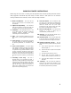
IMPORTANT SAFETY INSTRUCTIONS Before using this unit, be sure to carefully read the applicable items of these operating instructions and the safety suggestions. Afterwards keep them handy for future reference. Take special care to follow the warnings indicated on the unit itself, as well as in the operating instructions. 1. Water and Moisture – Do not use the unit near any source of water or in excessively moist environments. 2.
User’s Guide LA-2A Universal Audio, Inc. PO Box 3818 Santa Cruz, CA 95063-3818 (831) 454-0630 voice (831) 454-0689 fax www.uaudio.com Universal Audio Part Number LA2A-M01. Revision 1.3 Notice This manual provides general information, preparation for use, installation and operating instructions for the Universal Audio LA-2A Leveling Amplifier. The information contained in this manual is subject to change without notice. Universal Audio, Inc.
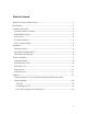
Table of Contents Teletronix LA-2A by Universal Audio................................................................................... ii Specifications .......................................................................................................................1 Operation of the LA-2A .......................................................................................................2 Input and Output Connections...............................................................................
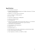
Specifications ! Gain Reduction: up to 40 dB ! Distortion: less than 0.35% total harmonics at +10 dBm, and less than 0.75% total harmonics at +16 dBm output ! Response: +/- 0.1 dB, 30 cycles to 15 kilocycles ! Noise: 75 dB below +10 dBm output level ! Gain: 40 +/- 1dB ! Output Level: +10dBm nominal, +16dBm peaks ! Input Level: +16 dBm maximum ! Very fast attack time ! Release Time: approximately 0.06 seconds for 50% release, 0.
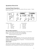
Operation of the LA-2A Input and Output Connections Input and Output connections are made using standard XLR style connectors. Terminal strips are also provided.
VU Meter Operation The VU Meter is used for both output level monitoring and gain reduction monitoring. When used to monitor the output level, the user may choose either +4 dB or +10 dB settings. The middle setting is for gain reduction, and the meter reads the amount of compression in dB. Limit / Compress Switch The Limit/Compress Switch changes the characteristics of the compressor IO curve. When in the Compress position, the curve is more gentle, and presents a low compression ratio.
Calibration Meter Zero Adjust The zero-adjust of the meter is set by the screw-adjust potentiometer located next to the Limit / Compress Switch. To adjust this, put the meter into Gain Reduction mode. Make sure that there is no signal present. Loosen the locking nut and use a screwdriver to adjust this potentiometer until the meter reads zero. Side-Chain Pre-Emphasis (R37) The LA-2A was designed for use in broadcast applications.
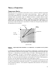
Theory of Operation Compressor Basics Before we dig in to a description of the LA-2A circuit, it is useful to examine the general characteristics of compressors and review some terminology. Figure 1 depicts the input/output characteristics of a compressor, an expander and a perfect amplifier. When operated within its specified range, an amplifier provides a constant amount of gain regardless of the level of the input signal. In Figure 1, the middle line depicts a perfect amplifier with a gain of 10 dB.
As an aside, an expander is a device which increases the dynamic range of a signal. For example, a 10dB change in the input signal might result in a 20 dB change in the output signal, thus “expanding” the dynamic range. There are several other terms related to compression that can be demonstrated by referring to Figure 2. The amount of compression or gain reduction is typically given in dB and is defined as the amount by which the signal level is reduced by the compressor.
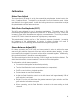
Figure 3 - Block diagram of the LA-2A compressor.
LA-2A Block Diagram A functional block diagram of the LA-2A is provided in Figure 3. A brief overview of the operation will be provided here. The input transformer provides isolation and impedance matching. After this the signal is fed into both the side-chain circuit and the gain reduction circuit. The side-chain is comprised of a voltage amplifier, a pre-emphasis filter, and a driver stage which provides the voltage necessary to drive the electro-luminescent panel.
stage. To see why this is true, we can look at the extreme cases. If the resistance is extremely high (this is the case when there is a small input signal and the light is off) then the photo-cell does not affect the circuit and there is no gain reduction. The second case we can look at is when there is a large signal present. In this condition, the light shines brightly and the photo-cell exhibits very low resistance.
The next important aspect is that of the release of the compressor. This is determined almost entirely by the characteristics of the photo-cell. The LA-2A uses cadmium-sulfide photo-cells. The first important aspect of the cell is its “two-stage decay”. After the light is removed from the cell, it releases quickly (40-80 milliseconds) to approximately half of its off resistance. The remainder of its release can take place over as much as several seconds. The next aspect is the “memory” of the cell.
Side-Chain Circuit The previously described gain reduction circuit is controlled by the control voltage which is supplied by the side-chain circuit. The LA-2A is a feed-back style compressor. This is due to the fact that the signal that is used to drive the side-chain circuit is affected by the gain reduced signal. This signal is first fed into the “Peak Reduction” potentiometer (R2), which controls the amount of side-chain drive and in turn controls the compression threshold and amount of gain reduction.
previously, the gain reduction is controlled by the photo-cell in the T4 el-op. In order to track the operation of this cell and determine the gain reduction, a second photo-cell is also illuminated by the same EL panel. This photo-cell is hand-selected to match the gain reduction photocell and hence gives an accurate indication of the amount of compression.
legendary Bill Putnam's company, Studio Electronics Corp shortly before he changed the company’s name to UREI®. Three different versions of the LA-2A were produced under the auspices of these different companies before production was discontinued around 1969. Developing the 1176 It was Bill Putnam himself who, in 1966, was responsible for the initial design of the 1176. Its circuit was rooted in the 1108 preamplifier which was also designed by Putnam.
currently mixing, I'm using both an 1176 and an LA2 on his voice, which is not unusual for me. "The 1176 absolutely adds a bright character to a sound, and you can set the attack so it's got a nice bite to it. I usually use them on four to one, with quite a lot of gain reduction. I like how variable the attack and release is; there's a sound on the attack and release which I don't think you can get with any other compressor.
Ken Kessie Mixer Ken Kessie (En Vogue, Tony! Toni! Tone!, Celine Dion) is known for being experimental. "Seems like everybody knows the basic tricks for he 1176," he says, "But here are two that might be lesser known. If you turn the attack knob fully counterclockwise until it clicks, the 1176 eases to be a compressor and acts only as an amplifier. Sometimes this is the perfect sound for a vocal.
inconsistent piece to piece than the 1176s, because of the tubes and the difference in fatigue of the tubes. "My big mentors were Andy Johns and Lee DeCarlo and Ron Nevision because they were all Record Plant guys. I learned how to make a rock and roll record from them. Although over the years it's become my own thing, my style still tends to be that Record Plant style, U87s, 1176s, LA-2As, 47 F.E.T.s...it's what I like.