
Operating instructions


5
Theory of Operation
Compressor Basics
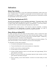
Before we dig in to a description of the LA-2A circuit, it is useful to examine the general
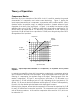
characteristics of compressors and review some terminology. Figure 1 depicts the
input/output characteristics of a compressor, an expander and a perfect amplifier. When
operated within its specified range, an amplifier provides a constant amount of gain
regardless of the level of the input signal. In Figure 1, the middle line depicts a perfect
amplifier with a gain of 10 dB. To see this, notice that a signal with an input level of –30
dB will result in an output level of –20 dB, which is an increase of 10 dB. Similarly, an
input level of 0 dB will result in an output level of 10 dB, hence the gain stays fixed at 10
dB regardless of the input level.
-30
-20
-10
0
+10
-30 -20
-10
0 +10
Input Level (dB)
Output
Level (dB)
Compression
Expansion
Perfect
amplifier
Figure 1 - Input/output characteristics of a compressor, an expander and a perfect
amplifier.
In contrast to an amplifier, whose job is to present a constant gain, a compressor varies its
gain in response to the level of the input signal. Large input signals result in less gain, thus
reducing or “compressing” the dynamic range of the signal. Referring again to the line
marked “compression” in Figure 1, we see that an input level of –30 dB results in an
output level of –20 dB, indicating a gain of 10 dB. Repeating this for input levels of –20
dB and –10 dB, we see that the compressor exhibits gains of 5 dB and 0 dB respectively.
From this, it is clear that the gain decreases as the input signal increases.
Referring to the diagram, we see that the compressor will increase its output level by 5 dB
for every 10 dB that we increase the input level. The compression ratio is defined as the
ratio of these two numbers. In this case the compression ratio would be 10:5, which can
be reduced to 2:1.