INSTRUCTION MANUAL 7510,7512 DURO SERIES Slicer WE THANK YOU FOR YOUR PURCHASE OF OUR MODEL 7510, 7512 SLICER.
7510/7512 TABLE OF CONTENTS DESCRIPTION PAGE Table of Contents List of Illustrations Introduction Installation Instructions Important Safety Warnings Operating Instructions Sharpening Instructions Operator's Care of Slicer / Lubrication Trouble Shooting Chart Mechanics Maintenance Repair, incl.
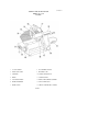
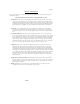
7510/7512 OVERALL VIEW OF MEAT SLICER MODEL 7510 - 7512 FIGURE 1 1 ON-OFF SWITCH 8 ADJUSTMENT SPACER 2 INDICATOR LIGHT 9 ELECTRIC CORD 3 CARRIAGE 10 CARRIAGE ARM KNOB 4 FENCE 11 CARRIAGE ARM 5 LAST SLICE DEVICE 12 REMOVABLE CHEESE SCRAPER 6 KNIFE SHARPENER 13 GRADUATED KNOB 7 KNIFE GUARD 14 SERIAL NAME PLATE (ON REAR) PAGE 2
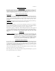
7510/7512 INSTRUCTION MANUAL INTRODUCTION This manual contains instructions for the Installation, Operation, Care, Maintenance and Repair of the Meat Slicing Machine. Disassembly, Replacement and Reassembly Instructions are included. A trouble shooting guide is provided. A complete Replacement Parts list with identifying figures is also included to facilitate identification and ordering of replacement parts.
7510/7512 OPERATION INSTRUCTIONS The Univex slicer is designed to meet the Cook's demand for an efficient, sturdy slicer. The Univex slicer will give unfailing performance over a period of years, when operated and maintained according to instructions contained herein. START/STOP SWITCH The slicer is started by pushing the start/stop toggle switch (Figure 1 [ 1 ]) upward to the ON position. A pilot light (Figure 1 [2]) is provided to indicate when the slicer is turned on.
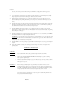
7510/7512 necessary, follow the procedure outlined on Page 5-6. Remember to unplug the electrical supply cord. (4) Loosen sharpener lock pin (Figure 3 [4]) which bears against sharpener post, then lift sharpener assembly (Figure 1 [6]) and rotate it 1/2 turn (180 degrees). Then seat it down over knife. (5) Tighten sharpener lock pin (Figure 3 [4]).
510/7512 WARNING: 5. 6. Wash body of slicer using warm water and mild soap using a soft cloth. Under no circumstances should the slicer be hose rinsed. It is recommended that the cloth be folded over a thin wooden stick when cleaning between the fence plate and the knife. Remove knife guard (Figure 1 [7]) by loosening knife guard knob (Figure 3 [2]) and pushing the long stud upward to lift the knife guard above surface of knife. Then carefully lift and remove guard. 7. Remove Knife deflector (Fig.
7510/7512 LUBRICATION INSTRUCTIONS MODEL 7510 - 7512 FIGURE 2 A PETROGEL, AS REQUIRED TO MAINTAIN LIGHT FILM, PAGE 7 B OIL MONTHLY, THREE DROPS MINERAL OIL.
7510/7512 TROUBLESHOOTING GUIDE 7510/7512 TROUBLE 1. Slicer will not operate. POSSIBLE CAUSE 1.1 Electrical service down. 1.2 Burned switch contacts. 1.3 Motor capacitor defective. 1.4 burned out motor REMEDY 1.1 Check electrical service. Replace fuse or reset circuit breaker as necessary. 1.2 clean or replace. 1.3 replace. 1.4 Remove, test, repair or replace 2. Motor running, blade 2.1 Belt tension too tight 2.1 Readjust belt tension. not turning.
7510/7512 MECHANIC'S MAINTENANCE Every year a mechanic or service technician should perform the following inspection and carry out the respective maintenance as required: FOR SAFETY, TURN OFF SLICER AND DISCONNECT ELECTRICAL CORD. 1. BELT DRIVE: This d rive features a multi-ribbed high performance belt for long trouble-free service. Inspect belt for proper tension. If glazed or excessively worn, replace. A tensioning device automatically allows for normal belt wear-in and stretching.
7510/7512 REPAIR INSTRUCTIONS (including disassembly, replacement and reassembly.) Always turn off slicer and disconnect electrical cord before doing any maintenance or repair on the slicer. Keep guards on all times. Keep slice adjustment fully closed so knife edge is not exposed. Keep sharpener assembly also in place so top of knife edge is not exposed. DRIVE BELT 1. Disconnect electrical power cord. 2. Remove four rubber suction feet (Figure 3 [37]) that secure bottom cover (Figure 3 [36]) to slicer.
7510/7512 KNIFE (Removal Figure 3) 1. Disconnect electrical power cord. 2. Loosen sharpener lock pin (Figure 3 [4]), then lift and remove sharpening unit. Set aside. 3. Remove knife guard knob (Figure 3 [2]) and carefully remove knife guard (Figure 3 [14]). 4. Using caution to avoid the sharp knife edge, remove the four screws (Figure 3 [12]) that secure knife (Figure 3 [15]). 5. Carefully remove knife and set aside with its flat side down flush on a bench so the edge is not exposed. 6.
7510/7512 SHARPENING STONES 1. Disconnect electrical cord. 2. Unscrew sharpener lock pin (Figure 3 [4]). 3. Lift up sharpening assembly (Figure 1 [6]) and remove from slicer. 4. Using an open end wrench, unscrew cover knob (Figure 4 [1]). It is recommended that a piece of tape or paper be temporarily wrapped around knob prior to unscrewing it so as to protect its finish. 5. Gently remove lever cover (Figure 4 [2]) off of mounting block (Figure 4 [26]).
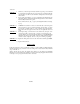
7510/7512 BASE AND KNIFE HOUSING ASSEMBLY MODEL 7510 - 7512 FIGURE 3 ILLUS. NO. PART NO. 1. 2. 3. 4. 5. 7510012 7510015 7510013 7510150 7510001 7512001 7510156 7510002 7510158 7510004 7510154 6509012 6509014 8512240 7510011 7512011 7510009 7512009 7510008 7512008 1012167 6. 7. 8. 9. 10. 11. 12. 13. 14. 15. 16. 17. 18. 19. 20. 21. 22. 23. 24. 25. 26. 27. 28. 29. 30. 31. 32. 33. 34. 35. 36. 37. 38. 39. 40. 41. 42. 43. 44.
7510/7512 BASE AND KNIFE HOUSING ASSEMBLY MODEL 7510 - 7512 FIGURE 3 PAGE 14
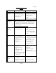
7510/7512 SHARPENER ASSEMBLY MODEL 7510 - 7512 FIGURE 4 ILLUS NO. 1 2 3 4 5 6 7 8 9 10 11 12 13 14 15 16 17 18 19 20 21 22 23 24 25 PART NO. 7510151A 6509153 6509151 6509150 6509149 6509125 6509137 7510120 8512728 6509147 6509127 6509128 6509129 6509130 6509131 6509134 6509133 6509135 6509136 6509132 6509143 8512516 6509142 6509141 6509126A DESCRIPTION SHARPENER ASSEMBLY WITH CONER KNOB, COVER COVER, SHARPENER NUT, COVER SPACER SPACER.
7510/7512 CARRIAGE ASSEMBLY MODEL 7510 FIGURE 5 ILLUS. NO. PART NO. DESCRIPTION 1. 8512432 SPACER, ADJUSTMENT 2. 8512436 STUD, ADJUSTMENT SPACER 3. 6509153 KNOB 4. 8512433* BUSHING ADJUSTMENT SPACER 5. 8512426 LAST SLICE DEVICE 6. 6509054 KNOB, LAST SLICE DEVICE 7. 8512428 SHAFT, LAST SLICE DEVICE 8. 8512427** BUSHING, LAST SLICE DEVICE 9. 8512425 CARRIAGE 10. 8512434 SHAFT, ADJUSTMENT SPACER 11. 8512431 NYLON TIP 12. 6509059 WASHER 13. 6509058 BOX NUT 14. 1200079 LOCKWASHER 15.
7510/7512 CARRIAGE ASSEMBLY MODEL 7512 FIGURE 5A ILLUS. NO. PART NO. DESCRIPTION 1. 8512432 SPACER, ADJUSTMENT 2. 8512436 STUD, ADJUSTMENT SPACER 3. 6509153 KNOB 4. 8512433* BUSHING ADJUSTMENT SPACER 5. 8512925 SUPPORT, LAST SLICE DEVICE 6. 8512924 KNOB, LAST SLICE DEVICE 7. 8512926 LAST SLICE DEVICE 8. 8512428 SHAFT, LAST SLICE DEVICE 9. 8512427** BUSHING, LAST SLICE DEVICE 10. 8512425 CARRIAGE 11. 8512438 NYLON TIP, ADJUSTMENT SPACER 12. 8512434 SHAFT, ADJUSTMENT SPACER 13.
7510/7512 CARRIAGE ARM AND SLIDE ASSEMBLY MODEL 7510 - 7512 FIGURE 6 ILLUS. NO. 1. 2. PART NO. 6509036 7510337. 6509035 8512229 7510434 7510326** 7510325 7510339 6509041 6509040 9512299 1053510 8512308 6509028 6509031 DESCRIPTION WASHER, SLIDE BAR RUBBER SPRING, SLIDE BAR (7512 ONLY) SPRING, SLIDE BAR (7510 ONLY) SCREW, M5-0.8 X 12MM FL HD SLT BAR, CARRIAGE SLIDE BUSHING, CARRIAGE ARM SUPPORT, CARRIAGE ARM SLIDE, CARRIAGE WASHER, CARRIAGE SLIDE BOLT, CARRIAGE SLIDE BUSHING ECCENTRIC SCREW, CAP M6-1.
7510/7512 SLICE ADJUSTMENT ASSEMBLY MODEL 7510 - 7512 FIGURE 7 ILLUS. NO. 1. 2. 3. 4. 5. 6. 7. 8. 9. 10. 11. 12. 13. 14. 15. 16. 17. 18. 19. 20. 21. 22. 23. 24. 25. 26. 27. 28. 29. 30. PART NO.
7510/7512 FENCE ASSEMBLY MODEL 7510 - 7512 FIGURE 8 ILLUS. NO 1. 2. 3. 4. 5. 6. 7 8. PART NO. 7510079 7512079 1200300 7510077 7512077 8512326 6509081 6509082 6509080 DESCRIPTION FENCE (MODEL 7510) FENCE (MODEL 7512) SHIMS ROLL PIN 3/16 X 2 BRACKET, FENCE MOUNTING (MODEL 7510) BRACKET, FENCE MOUNTING (MODEL 7512) SET SCREW NUT, ACORN WASHER STUD, FENCE PAGE 20 QTY.
7510/7512 MOTOR. MOUNT AND DRIVE ASSEMBLY MODEL 7510 - 7512 (115V, 50/60HZ, 1PH) (100V, 50/60HZ, 1PH) FIGURE 9 ILLUS. NO. PART NO. 1. 2. 3. 4. 5. 6. 7. 8. 9. 10. 11. 12. 13. 14. 15. 6090000 4400085 1200076 7120034 4400183 1200058 7510099 7120006 7510157 1200261 1200260 4400127 7120033 7510252 7512155 7510153 6509156 6509098 1200060 6509104 7120022 6509041 6509040 4400188 4400023 16. 17. 18. 19. 20. 21.* 22.* 23. 24. DESCRIPTION QTY. MOTOR, 1/3 HP, 115V, 50/60HZ, 1PH TUBING, CORD WASHER NO.
7510/7512 MOTOR.
7510/7512 TRANSFORMER / CAPACITOR PANEL 100V,50/60HZ,1PH FIGURE 9A ILLUS. NO. 3 12 25 26 27 28 29 30 31 32 33 34 35 36 37 38 39 PART NO. 1200076 4400191 4400065 7120017 4400101 4400053 1212042 7120001 4400024 7120008 6509113 6509161 7100117 1200060 7100118 400414 200012 DESCRIPTION WASHER, NO. 10 WASHER, RUBBER WASHER, LOCK NO. 10 NUT, M5-0.8 CLAMP, CABLE CORD, ELECTRICAL STRAIN, RELIEF CAPACITOR, 20MFD, 370V, 50/60HZ, 115V BRACKET, CAPACITOR BOOT, CAPACITOR STUD. M5-0.8 X 40MM STUD. M5-0.
7510/7512 MOTOR. MOUNT AND DRIVE ASSEMBLY MODEL 7510 - 7512 220-240V, 50/60HZ, 1PH FIGURE 10 ILLUS. NO. PART NO. DESCRIPTION 1. 2. 3. 4. 5. 6. 7. 8. 9. 10. 11. 12. 13. 14. 15. 6090002 MOTOR 1/3HP, 220-240V, 50/60HZ, 1PH 4400085 TUBING, CORD 1200076 WASHER NO. 10 7120034 BRACKET, LEFT 4400183 LOCKWASHER NO. 8 1200058 NUT 8-32 7510099 BOLT, MOTOR PIVOT 10.MM SPECIAL 7120006 SPACER 7510157 BRACKET, MOTOR PIVOT 4400005 LOCK WASHER 7510251 SCREW, SOCKET HD.
7510/7512 MOTOR.
7510/7512 CAPACITOR PANEL 220240V, 50/60HZ, 1PH Figure. 10A ILLUS. NO. 1 2 3 4 5 6 7 8 9 10 11 12 13 14 15 16 17 PART NO. 7120052 1200076 1200415 6509113 1200430 1200429 1814062 4400065 7120017 7120055 1200093 4400204 7120051 7120056 7120008 1200060 4400224 DESCRIPTION PANEL, CAPACITOR WASHER, FLAT NO. 10 SCREW, HEX HD 10-32 X 1 1/4 STUD, M5-0.8 X 40MM WASHER, LOCK N0.6 NUT, HEX 6-32 WASHER, FLAT M5 WASHER, LOCK NO. 10 NUT, HEX M5-0.8 RELAY WASHER, FLAT N0.
7510/7512 WIRING DIAGRAM MODEL 7510 - 7512 115V, 50/60 HZ, 1PH FIGURE 11 IMPORTANT Before making electrical connections, check the specifications on the data plate to assure they agree with those of your electrical service. Whenever cleaning or maintenance is being performed DISCONNECTelectrical cord.
7510/7512 WIRING DIAGRAM MODEL 7510 - 7512 220-240V, 50/60HZ, 1PH FIGURE 11A IMPORTANT Before making electrical connections, check the specifications on the data plate to assure they agree with those of your electrical service. Whenever cleaning or maintenance is being performed DISCONNECT electrical cord.
7510/7512 WIRING DIAGRAM MODEL 7510 - 7512 100V, 50/60HZ, 1PH FIGURE 11B * CAUTION: Installations with 50HZ electrical supplies should have black motor lead connected to 110V output terminal ONLY. Connection to higher voltage outputs could cause motor failure. The transformer has been wired at the factory for 50HZ operation at 110V output. If you have 60HZ electrical supply the black motor lead can be switched to 115V output terminal for optimal slicer performance.