nivex Exxacting Standards, E acting S tanda rds, JJust ust LLike i ke YYours, ou rs, ssirce ince 11948 948 SRM20/SRMF20 SRM2O/SRMF2O SRM20/SRMF20 Swing Ring Swing Ring Series Series S RM20/SRMF20 PPLANETARY LANETARY M IXERS SRM2O/SRMF2O MIXERS Maintenance & Parts Manual Persons under the age of 18 are not permitted to operate or have Persons accessibility to operate this equipment per U.S. Dept. of Labor Employment Standards Administration Fact Sheet No. ESA91-3. ESA91-3.
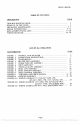
SRM2O - SRMF2O TABLE OF CONTENTS PAGE DESCRIPTION TROUBLE SHOOTING GUIDE REMOVAL OF TOP COVER MECHANICS MAINTENANCE REPAIR INSTRUCTIONS REPLACEMENT PARTS, LISTS WIRING DIAGRAMS 3 4 4- 5 6 - 10 11 - 22 23 -25 LIST OF ILLUSTRATIONS PAGE ILLUSTRATION OVERALL VIEW OF MIXER LUBRICATION INSTRUCTIONS TRANSMISSION FIGURE 3 FIGURE 4 BEATER HEAD ASSEMBLY FIGURE 5 POWER TAKE OFF ASSEMBLY FIGURE 6 INPUT ASSEMBLY FIGURE 7 VERTICAL SHAFT ASSEMBLY FIGURE 8 BOWL LIFT ASSEMBLY FIGURE 9 BOWL SUPPORT ASSEMBLY SPEED C
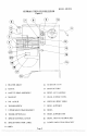
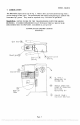
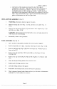
SRM2O - SRMF2O OVERALL VIEW OF FOOD MIXER Figure 1 12. START BUTTON 2. CHUTE 13. STOP BUTTON 3. SAFETY RING ASSEMBLY 14. BOWL LIFT HANDLE 4. MAGNET 15. REAR ACCESS PANEL 16. SHIPPING BOLT FIOLE 1. 5. BEATER SHAFT NO. 12 HUB 6. THUMB SCREW 17. BOWL SUPPORT 7. UPPER MOUNTING BRACKET 18, BOWL 8. TIMER (OPTIONAL) 19. BOWL SUPPORT PIN 9. 10. SPEED CONTROL LEVER 20. BOWL MOUNTING BRACKET SPEED INDICATOR LABEL 21. LOWER MOUNTING BRACKET 11.
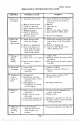
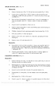
SRM2O - SRMF2O SRM2O/SRMF2O TROUBLESHOOTING GUIDE TROUBLE 1. Mixer will not operate. REMEDY POSSIBLE CAUSE 1.1 Check electrical service. Replace fuse or reset circuit breaker as necessary. 1.2 Replace. 1.3 Turn timer on. 1.4 Replace 1.5 Remove, test, repair or replace. 1.6 Install SAFETY RING ASSY 1.1 Electrical service down 1.2 Burned switch contacts 1.3 Timer not turned on 1.4 Motor capacitor defective 1.5 Burned out motor 1.6 SAFETY RING not mounted and closed. 1.7 Bowl not raised 2.
SRM2O - SRMF2O REMOVAL OF TOP COVER The top cover (Fig. 12 [16]) must be removed in order to perform the maintenance operations. It is secured by a spring clip at its front end and a screw at its rearward end. First, DISCONNECT THE ELECTRICAL POWER FOR SAFETY. Then, remove the screw in the rear (Fig. 12 [20]), lift rear of cover, push forward about 3 inches and lift cover off. Re-install in reverse procedure using care to insure that the cover sits squarely and uniformly on the mixer housing.
SRM2O - SRMF2O 4. LUBRICATION The lubrication instructions are in Fig. 2. Motors have pre-lubricated bearings with a service interval often years. The transmission and beater head gearing are packed with Nevastane 5p7 grease. They must be repacked every 500 hours of operation. WAINING: NEVER WORK ON THE TRANSMISSION WITH THE MIXER RUNNING. IT IS RECOMMENDED THAT THE ELECTRICAL SERVICE BE DISCONNECTED TO PREVENT ACCIDENTAL START UP.
SRM2O - SRMF2O REPAIR INSTRUCTIONS (Including disassembly, replacement and reassemble) TRANSMISSION (Fig. 3) Removal WARNING: DISCONNECT POWER FOR SAFETY. Remove housing top cover (Fig. 12 [16]). Adjust speed control to low speed, then back to high speed, remove upper retainer bracket (FIG. 11 [15]), and upper V-belt (Fig. 11 [11]) from transmission driven pulley (Fig. 11 [12]). Remove driven pulley. CAUTION: Transmission assembly is heavy and must he supported prior to removing.
SRM2O - SRIvÍF2O 3. Input Assembly (Fig. 6) Remove two cap screws (Fig. 6 [10]) and withdraw assembly from transmission. Remove retaining ring (I), gear (2), keys (5, 7), retaining rings (1) and press shaft (6) and bearing (4) from housing (8). e. Remove retaining rings (3) and press bearing (5) from housing (6). d. Remove retaining ring (1) and press shaft (6) from bearing (4). 4. Vertical Shaft Assembly (Fig. 7) Remove key (4).
SRM2O - SRMF2O e. Lubrication of the transmission should be done following its installation on the mixer. Apply Keystone Nevastane 5P7 grease to the spur gear and bevel gear meshes. This may be simplified by feeding the grease into the rotating gear meshes. Caution should be exercised to avoid entrapment of the application implement in the gear teeth, Insure the deflector (Fig. 5 [5]) is positioned to dynamically guide the lubrication into the bevel gear mesh. BOWL SUPPORT ASSEMBLY (Fig.
SRM2O - SRMF2O SPEED CONTROL ASSY. (Fig. 10) .jumbly Remove housing cover (Fig. 12 [16]) and rear access panel (Fig. 12 [23]). Loosen screw on collar (Fig. 10 [17]). Remove collar rod end (16) and o'ring (Fig II [8]) from cam assembly (lI). Loosen set screws (10) in cam assembly (Il). Drive roll pin (4) from hub (3) and pull hub (3), lever (2), and handle (1) from cam assembly shaft (Il). Remove washer (5) from cam assembly (Il) Unscrew hub (3) and handle (1) from lever (2).
SRM2() - SRMF2O Unwrap belt (21) fi-orn pulley (27). Withdraw belt (2 1) from van-speed pulley (10). Loosen screws on contactor (Fig. 12 [32]) which secure motor cord power leads (34). Remove nut (38), lock washer (37) and motor cord ground lead from weld stud. Remove nuts (38), washers (36) arid cord clamps (35). Remove nuts securing motor (30) and lift motor from mixer. Loosen set screw (28) and slide pulley (27) and key (29) off motor shaft.
SRM2O - SRMF2O TRANSMISSION FIGURE 3 ILLUS. 1. 2. 3. 4. 5. 6. 7 8. 9. 10 11. 12. 13. 14. 15 16 PART NO. DESCRIPTION 1024434 1024117 1200012 1024041 1200076 4400065 8800022 1200084 1200085 1200057 4400194 1200440 1020011 4400342 4400343 1012438 1012439 Transmission Housing Transmission Cover Phillips Hd. Screw 10-32 x 1/2 Spring Clip Steel Flat Washer #10 Split Lock Washer #10 Foam Strip Steel Flat Washer 1/2 Split Lock Washer 1/2 Socket, Hd. Cap Screw 1/2-20 x 1 Dowel Pin 1/4" OD. x 1/2" LG Hex Hd.
SRM2O - SRMF2O BEATER HEAD ASSEMBLY FiGURE 4 ILLUS. 1 2 3 4 5 6 7 8 9 10 11 12 13 14 PART NO. DESCRIPTION 1023075 1200381 1023014 1200113 1030019 1200119 1012003 1200117 1012012 8900038 1020106 4400499 1200051 1020002 4400269 Beater Head Assembly Drive Pin 3/8" x 1-1/4" Beater Head Shaft Woodruff Key #9 BaIl Bearing 6204LL Retaining Ring, External Beater Head Gear Retaining Ring, Internal Beater Head Spacer Set Screw Beater Head Casting Washer 7/16" x 1-118" X 5/64' Hex. Hd.
SRM2O - SRMF2O POWER TAKE OFF ASSEMBLY FIGURE 5 ILLUS. PART NO. QTY DESCRIPTION 1. Cover, PTO. (With PTO ) 2. 3. 4. Adapter, Attachment (With PTO ) Retaining Ring, External 8800033 8800012 1200119 4400030 1012446 1024417 5 4400005 6. 1200075 7. 1200025H 8. 1030019 9. 1200117 10. 1030031 11. 1020004 12 1021016 13. 1024420 1200113 14. 4400006 15!' 16,* 4400016 1200103 17. 4400229 18. 4400210 19. 8900019 20. 1200022H 21. * Not available 1 5 Housing, PTO.
SRM2O - SRMF2O INPUT ASSEMBLY FIGURE 6 ILLUS. 102 1036 1. 2 3. 4. 5. 6 7. 8. 9. 10. 11. QTY. PART NO. DESCRIPTION 1200119 1020010 1200117 1030019 1200113 1024186 4400230 1030017 4400003 1200022H 4400005 Input Assembly Retaining Ring, External Spur Gear, Input Pinion Only Retaining Ring, Internal Ball Bearing 6204LL Woodruff Key #9 Input Shaft Key 3/16" sq. x 1-1/2 1g. Input Housing 6 2 2 Steel Flat Washer 14 ID. 2 Hex. Hd.
SRM2O - SRMF2O VERTICAL SHAFT ASSEMBLY FIGURE 7 ILLUS. 1 2 3 4 5 6 7 8 QTY. PART NO.
SRM2O - SRN1F2() BOWL LIFT ASSEMBLY FIGURE 8 ILLUS. 1 2*** 3 4 5 6 7 8 ** 9* 10 11 12 13 14 15 QTY. PART NO.
SRM2O - SRMF2O BOWL SUPPORT ASSEMBLY FIGURE 9 LUS. 1 2 3 4 5 6 7 8 9* 10 11 12 13 14 15 16 17 PART NO. DESCRIPTION 1021028 4400219 1021019 4400278 1012190 1012181 1012202 1200311 1023053 1012189 1012191 4400127 1200063 1200039 4400178 1200077 1020091 Bowl Support Pin, Bowl Support Slide Cover, Movable Gasket Strip Frame, BL. Pin, Rod End Rod End 3/8-24 L.H. Retaining Ring, External Connecting Rod, BL. Slide, BL. Gibb, BL. Steel Flat Washer 3/8 Kep Nut 5/16-18 Hex Hd.
SRM2O - SRMF2O SPEED CONTROL ASSEMBLY FIGURE lo ILLUS. 1 2 3 4 5 6 7 8 9 10 II 12 13 14 * 15. 16 17 18 19 20 21 22 PART NO. DESCRIPTION 4400202 1020066 1012137 1200300 Handle Lever, S.C. Hub, S.C. 1200301 1020068 4400127 1200063 1200156 1200304 1020069 1023222 1200471 1030223 1200155 1012201 1020441 1030318 1023223 4400208 4400005 1023225 QTY. Roll Pin 3/16' x 2" Nylon Washer 5/8 Speed Control Bearing Steel Flat Washer 3/8 Kep Nut 5/16-18 Spring Washer 5/8 Set Screw 10-32 x 3/4 Cani Assy, S.
SRM2O - SRMF2O ILLUS. PART NO. I 12001 19 2 1030019 3 12001 17 4 1030167 1012181 5 6 7 8 9 10 11 12 13 14 15 16 17 * 18 19 20 21 22 23 24 25 26 27 28 29 30 12003 1 i 1012202 4400009 1021022 1020061 1020501 1020500 1200063 VARI-SPEED ASSEMBLY FIGURE 11 DESCRIPTION Retaining Ring, External BalI Bearing 6204LL Retaining Ring, Internal Pulley Swivel Bracket Rod End Pin Retaining Ring, External QTY. 2 2 2 I i 4 Rod End 3/8-24 LU.
SRM2O - SRMF2O VARI-SP EED ASSEMBLY FIGURE 11 Page 20 PDF compression, OCR, web optimization using a watermarked evaluation copy of CVISION PDFCompressor
SRM2O - SRMF2O LUS. PART NO.
SRM2O - SRMF2O 44 45 46 47 48 49 50 51 52 53 4400079 7100028 1033326 4400171 120002211 4400057 4400005 1200450 1024430 1024431 Screw CHZ HD M4-.
SRM2O - SRMF2O WIRING DIAGRAM 115/208-230V, 60HZ, IPH 220-240V, 50HZ, 1PH 100V1 50160HZ, 1PH FIGURE 13A TIMER / (OPTIONAL) r GND 1 I Al I L_ ___J W3 MAGNETIC LII L2 L3© I3 I CONT ACT OR I BOWL LIFT RIGHT GUARD Lj r L2 WHT W9 -1 LEFT GUARD1 SWITCH LI BLK W) W2 POWER IN SWITCH r -1 SWiTCH I A2 TI )4I T2 J WIO J W4 W7 W5 WI START STOP SWITCH SWITCH WI I MOTOR [iI1 W6 LffJ WIRE TABLE PART WIRE NUMBER NO.
SRM2O - SRMF2O WIRING DIAGRAM 115V, 60HZ, 1PH FOR CANADIAN ONLY 220-240, 50HZ, 1PH FOR EUROPE ONLY FIGURE 13B ri POWER IN TIMER lop TIONALI LEFT GUARDi SWITCH L2 WI W2 GND WI I L STARTER W3 RIGHT GUARD r SWITCH Li r Is0 L_ __-_J W5 BOWL LIFT SWITCH i rii W6\r"iII \\ STOP SWITCH START SWITCH I I WIRE TABLE PART WIRE NUMBER NO.
SRM2O - SRMF2O WIRING DIAGRAJ\I 380-400v, 50Hz, 3PII FIGURE 13C (For Europe Only) WIT POWER IN WI2 L2 L3 GND LI H3H2 H TIMER W2 WI r LEFT GUARD WI I W9 SWITCH A LI O SWITCH -r LJ A21 BOWL LIFT RIGHT GUARD L2 STARTER W3 r- CONTROL TRANSFORMER r SWITCH i Ql L Q (\ O Q T3 T2 TI T2 T3 96 14 L -J WIO J W4 W5 W7 STOP SWITCH START SWITCH WI4 b RIi MO TOR W8 WIRE TABLE PART WIRE NUMBER NO.