
Troubleshooting guide

SRM2O - SRMF2O
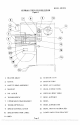
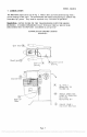
REMOVAL OF TOP COVER
The top cover (Fig. 12 [16]) must be removed in order to perform the maintenance
operations. It is secured by a spring clip at its front end and a screw at its
rearward end. First, DISCONNECT THE ELECTRICAL POWER FOR SAFETY.
Then, remove the screw in the rear (Fig. 12 [20]), lift rear of cover, push forward
about 3 inches and lift cover off.
Re-install in reverse procedure using care to insure that the cover sits squarely
and uniformly on the mixer housing.
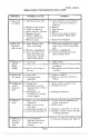
MECHANICS MAINTENANCE
Every six months a mechanic should perform the following inspection and maintenance as
required:
1. BELTS
WARNING: Start mixer and adjust speed control (Fig.
1 [9)) to speed 4. Stop
mixer. FOR SAFETY' DISCONNECT POWER.
Remove top cover (Fig. 12 [16]) and rear access panel (Fig. 12 [23 J).
e. Check belts (Fig. ii
[11 & 21]). If broken, glazed or worn, replace.
d Check belt (Fig. 11 [11]) for proper tension. The outer edge of the belt should be
flush with the outer diameter of the variable speed pulley (Fig. 11 [10)).
If not,
adjust by loosening the Jam Nut (Fig. 10 [15 J) and turning the connecting rod
(Fig. 10 [14]) until the outer edge of belt is flush with the outer diameter of the
pulley. Retighten Jam Nut.
WARNING: Plug machine in, start mixer, and adjust speed control to speed 1.
Stop mixer. FOR SAFETY, DISCONNECT POWER.
Check belt (Fig. 11 [21)) for proper tension. The outer edge of the belt should he
flush with the outer diameter of the variable speed pulley (Fig. Il [10)).
If not,
adjust by loosening nuts (Fig. 11 [13 J), holding motor (Fig. 11(30)), raise or
lower the motor until the outer edge of belt is flush with the outer diameter of
pulley. Retighten Nuts.
2. MOTOR
Check motor (Fig. 11(30]) for overheating, noise and excessive end play of shaft.
Replace if defective.
3. BOWL LIFT ADJUSTMENT (Fig. 8 and 9)
Place 20 qt. mixing bowl (Fig. 1 [18]) on bowl support and 20 qt. batter beater on
beater shaft (Fig. 1 [1]).
Raise bowl support to the high position.
e. Check clearance between bottom of bowl and lowest point of batter beater.
Clearance should be 3/16 inch, plus or minus 1/16 inch.
d. If adjustment is required, disconnect power, loosen lock nut (Fig. 8 [lO]) and (urn
linkage rod (Fig. 8 [9]) until desired clearance is obtained. Retighten lock nut.
Page 4
PDF compression, OCR, web optimization using a watermarked evaluation copy of CVISION PDFCompressor