Part I. User’s Guide 1. Introduction............................................................................................. 2 1.1 System Feature ................................................................................................................................3 1.1.1 Front View............................................................................................................................3 1.2.2 Front Panel Controls and Indicators...............................................
4.2 Jumper Setting .............................................................................................................................. 50 4.2.1 PCI-X Speed Setting(J22, J26) .............................................................................................. 51 4.2.2 VGA Enable / Disable(J18) ................................................................................................... 52 4.2.3 Clear CMOS Header ......................................................................
Preface The information in this User's Guide has been carefully reviewed and is believed to be accurate. The vendor assumes no responsibility for any inaccuracies that may be contained in this document, makes no commitment to update or to keep current the information in this Guide, or to notify any person or organization of the updates. NOTE: For any up-to-date version of this document, please see our web site at www.uniwide.com. UNIWIDE Technologies, Inc.
1. Introduction The key objective for UniServer is to overcome the major challenges faced by developers, and system integrators alike, in deploying ideal server solutions to the market. Although many, key challenges are identified as reliability, performance, value, scalability and manageability. UniServer offers the best in class for each of these challenges by employing the latest technology designed by a specialized sever team.
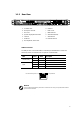
1.1 System Feature 1.1.1 Front View a. Slim CD-ROM Drive d. Hard Disk Drive b. Front Panel Controls and Indicators e. Front Bezel c. FDD Ejector button f. Mounting Bracket 1.2.2 Front Panel Controls and Indicators a. USB 2,0 Ports e. System Fault LED b. Power LED f. System ID Switch c. LAN Activity LED g. Reset Switch d. System ID LED h.
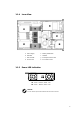
1.1.3 Rear View a. AC Power Inlet h. USB Port b. PCI-Express x16 Slot i. c. PCI-X Slot j. IEEE 1394 Port d. System Geographical ID Switch k. GbE LAN Port(IPMI) e. VGA Port l. f. Serial Port m. External SAS Port KVM over IP GbE LAN Port g. PS/2 Keyboard / Mouse Port LAN Port Function The LAN port uses a CAT 6 LAN cable for connecting the motherboard to a local area network by means of a network hub. The port has 2 indicator LEDs.
1.1.4 Inner View a. Power Supply e. Memory DIMM Slots b. Silm FDD f. Heatsink c. Silm CD-ROM g. PCI-Express Add-on Card d. CPU Air Duct h. PCI-X Add-on Card 1.1.5 Power LED Indication AC : Green – Normal / Yellow - Fail DC : Green – Normal / Yellow - Fail NOTICE You can check the power status LED after the front bezel is removed.
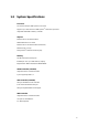
1.2 System Specifications Processor Two socket F(1207pin) AMD OpteronTM Processors Supports up to 2P/4C Dual-Core AMD OpteronTM 2000 Series processors Integrated 128bit DDR-2 memory controller Chipset NVIDIA® nForceTM Professional 2200 AMD-8132TM PCI-X 2.
Drive Bays Supports 2 hot-swap SATA HDDs (1522VA-01, 1522VA-02) Supports 2 hot-swap SAS HDDs (1522ES-01) Supports Slim CD-ROM and Slim FDD Drive Expansion Slots One x16 PCI-Express slot supporting half-length add-on card One 64bit 133/100/66MHz PCI-X slot supporting half-length add-on card (1522VA-02) One 64bit 100/66MHz PCI-X slot supporting half-length add-on card (1522ES-01) Integrated I/O Rear I/O One VGA port One serial port One PS/2 keyboard & mouse port Two USB 2.
LAN Controller Two Broadcom® BCM5721 PCI-Express gigabit ethernet controllers Support PXE function Video Controller XGI Volari Z9 /16MB BIOS AMI BIOS Support ACPI 2.0 with S0/S1/S3/S4 and S5 Support AMD PowerNow! 48-bit LBA support Support USB K/B & Mouse Serial Console Redirection Support USB boot and PXE boot in boot sequence Support serial over LAN function Power Supply 500W cold-swap single power supply with PFC function AC Input: 100-240V~, 50/60Hz, 9.0-4.5A Form Factor 1U (H x W x D): 43.
1.3 Mainboard Layout 1.3.
1.3.2 Mainboard Layout ① AMD® OpteronTM Socket 1207 - CPU0 ® ② AMD Opteron TM Socket 1207 - CPU1 ⑨ PCI Express x16 Slot ⑩ Two Broadcom® PCI Express GbE ports ③ Registered ECC DDR memory Slots ⑪ LSILogic LSI1068X 8-ch SAS controller ④ NVIDIA nForceTM Professional 2200 ⑫ 32pin SAS Connector ⑤ NVIDIA nForceTM Professional 2050 ⑬ External SAS Connector ⑥ AMD® 8132 PCI-X 2.
2. Important Safety Only a technically qualified person shall access, integrate, configure, and service this product. To avoid personal injury or property damage, read, observe, and adhere to all of the following safety instructions and information before you begin installing the product. 2.1 Intended Application Uses This product was evaluated as information technology equipment (ITE), which may be installed in offices, schools, computer rooms, and similar commercial type locations.
2.3 Earth-Grounded Socket Outlets CAUTION To avoid electrical shock, the system power cord(s) must be plugged into socket-outlet(s) that is provided with a suitable earth ground. The system will be provided with the following marking: z 2.4 Connect only to properly earthed socket outlet. Before Removing the Access Covers CAUTION To avoid personal injury or property damage, the following safety instructions apply whenever accessing inside the product: 2.
2.7 z Avoid moving around unnecessarily. z Hold the server components (especially boards) only by the edges. z Place the server components on a grounded, static-free surface. z Use a conductive foam pad if available but not the component wrapper. z Do not slide the components over any surface. Cooling and Airflow CAUTION For proper cooling and airflow, always install all access covers before turning on the system.
3. System Installation 3.1 Preparing for Setup 3.1.1 Unpacking ① Main Box ② Slide Rail Box ③ Heatsink Pad ④ Accessory Box ⑤ Heatsink Box ⑥ System Bottom Cushion ⑦ UniServer 1522 System ⑧ System Top Cushion CAUTION In setting the product out of the box, hold it in the middle and not the cushion. Depending on the weight of the product, two people together should lift it.
3.1.2 Packing List Unpack the package and check if all items listed below are present. If any item contained in the package is damaged or missing, please contact your local dealer for replacement. In addition, keep the box and packing materials for possible future use.
3.1.3 Environmental Specifications Place In front of the system, minimum 25" of the space is needed for using and managing the system. In rear of the system, minimum 30" of the space is needed for managing the system and airflow. Power supply Before installing the system, check the power capacity of the place where the system is installed. Grounding The system should be grounded. Temperature The system should be installed where the airflow and temperature is proper.
3.1.4 Install Rail for Mounting the System on the Rack This section provides information on installing the system into a rack unit with the slide rails provided. Slide Rail Slide rails consist of two sections: an inner fixed chassis rail that secures directly to the server chassis and an outer fixed slide rail that secures directly to the rack itself. You should have received outer slide rails in the rack mounting kit.
Installing the Outer Rails As shown in picture below, put the rear of outer rail on right place of the rear-mounting frame, and fit it on the front-mounting frame. You can fit the outer rails on the rack very easily and then eventually you can reduce the assembly time. Finally, secure it with M6 screws, just rear side only.
3.1.5 Install System at the Rack Cabinet CAUTION Remove all the cables from system before installing. CAUTION System can be heavy. To reduce the risk of personal injury or damage to the equipment, get help to lift and stabilize the system during installation or removal, especially when the system is not fastened to the rails.
3.2 Installing User Serviceable Component 3.2.1 CPU System mainboard accommodates Socket-F(1207 pin) AMD Opteron TM Processors at 2000 MT (Mega Transfer per second). You must insert a CPU into CPU socket 0 (CPU0) first before installing one in CPU socket 1 (CPU1). The correct CPU installation sequence is CPU0, CPU1. CAUTION If you are using 1522VA-01, 1522ES-01 model, you must surely use two for appropriate operation. Follow these instructions to install the CPU.
3.2.2 Memory The system mainboard uses Dual Inline Memory Modules (DIMM). Two pair's banks are available; each bank supports one CPU with Hyper Transport Technology. The memory DIMMs accommodates Registered ECC (400/533/667) SDRAM DIMM and Double Data Rate Memory (DDR2) memory modules in 128MB, 256MB, 512MB, 1GB, and 2GB, 4GB combinations. Total memory size for one CPU is up to 32GB. CAUTION The system mainboard has strict memory type and timing requirements.
Memory Installation Procedure ① Locate the DIMM modules. ② Make sure the DIMM’s pins are facing down, and check that the pin arrangement on the memory module resembles the one pictured below. CAUTION Always populate H0 DIMM socket before installing memory modules in the H1 DIMM sockets. ③ Insert the module into the DIMM socket and press down evenly on both ends firmly until the DIMM module is securely in place.
23
3.2.3 Hard Disk Drive NOTICE When you install hard disk drive into the system, we recommend using slot #0 first.
3.2.4 PCI Add-on Card WARNING Power off power supply completely when adding or removing any expansion card and other system components. Failure to do so may cause severe damage to both your motherboard and expansion card. WARNING Check add-on card type for sure when adding expansion card to slot. PCI-X slot can not support exclusive 5V add-on card. 3.2.4.1 Memory Installation Procedure Pull out the latch toward the direction as shown in picture below and rotate the latch clockwise.
4. BIOS and Jumper Setting 4.1 BIOS This chapter discusses the AMI BIOS Setup program built into the ROM BIOS. The Setup program allows users modifying the basic system configurations according to their requirements. This special information is then stored in battery-backed RAM so that it retains the Setup information when the power is turned off. The AMI BIOS installed in your computer system's ROM (Read Only Memory) is a custom version of an industry standard BIOS.
4.1.2 Updating BIOS Setup Creating a bootable floppy disk A. DOS environment Insert a 1.44 MB floppy disk into the drive. At the DOS prompt, type: format A : /S then press . B. Microsoft® Windows® environment(Microsoft® Windows® 95/98 only) Insert a 1.44 MB floppy disk into the floppy disk drive. From your Windows desktop, click on Start, then select My Computer. Select the 3 1/2 Floppy Drive icon. Click File from the menu, and then select Format. A Format 3 1/2 Floppy Disk window appears.
4.1.3 Using Setup In general, you use the arrow keys to highlight items, press to select, press to quit. The following table provides more details about how to navigate in the Setup program using the keyboard. Key Function Up Arrow(↑) Key Move to the previous item Down Arrow(↓) Key Move to the next item Left Arrow(→) Key Move to the previous item Right Arrow(←) Key Move to the next item Esc key In the Submenu: Exit the submenu.
4.1.4 Main Menu This is the first screen that is displayed when you enter the BIOS Setup Utility. Each tab lined on the top of the screen represents each different menu. The following picture shows the main menu. Main menu shows the information of BIOS version, date and ID; processor type, speed and count; system size. In addition, system time and date is adjustable using + / - key or number keys. NOTICE You can check the BMC F/W version on the post and in the BIOS setup utility 4.1.
4.1.5.1 CPU Configuration Submenu In CPU configuration, you can set up CPU frequency and enable/disable the Error Reporting. GART error reporting should remain disabled for the normal operation. Feature Options Description GART Error Reporting Disable Enable This option should remain disabled for the normal operation. This driver developer may enable it for testing purpose.
4.1.5.2 IDE Configuration Submenu You can make the selections on IDE Configuration menu.
4.1.5.3 Floppy Configuration Submenu Feature Options Description Floppy Configuration Disabled 5 1/2” 360 KB 5 1/2” 1.2 MB 3 1/2” 720 KB 3 1/2” 1.44 MB 3 1/2” 2.88 MB Select Floppy A or Floppy B and then selects floppy-diskette type installed in your system.
4.1.5.4 Super IO Submenu Feature Options Description OnBoard Floppy Controller Disabled Enabled Allows BIOS to Enable or Disable Floppy Controller Serial Port1 Address Disabled 3F8/IRQ4 3E8/IRQ4 2E8/IRQ3 Allows BIOS to Select Serial Port1 Base Addresses. Serial Port2 Address Disabled 2F8/IRQ3 3E8/IRQ4 2E8/IRQ3 Allows BIOS to Select Serial Port1 Base Addresses.
4.1.5.5 ACPI Configuration Submenu Feature ACPI Configuration 4.1.5.6 Options ACPI Aware O/S Yes/No Description Enable: O/S supports ACPI Disable: O/S doesn’t support ACPI Hyper Transport Configuration Submenu To set up the hyper transport speed and bandwidth, you can adjust over this menu. The incorrect manipulation will impede the system running.
4.1.5.7 IPMI Configuration To set up the BMC LAN Configuration, you can adjust over this menu. 4.1.5.
4.1.5.9 PCI Express Configuration Submenu Enable/Disable PCI Express L0 and L1 link power states. 4.1.5.
4.1.5.11 USB Configuration Submenu Feature Options Description USB Controller Support Disabled USB 1.1 Only USB 1.1+ USB 2.0 Enables USB controller Legacy USB Support Disabled/Enabled/ Auto Enables support for legacy USB Auto option disables legacy support if no USB device connected USB 2.0 Controller Mode HiSpeed FullSpeed Configures the USB 2.0 controller in HiSpeed(480Mbps) or FullSpeed(12Mbps).
4.1.5.
4.1.
Feature Plug & Play O/S Options Yes No Description Yes: lets the O/S configure PnP devices not required for boot if your system has a Plug and Play O/S PCI Latency Timer 32, 64, 96, 128, 160, 192, 224, 248 Value in units of PCI clocks for PCI device latency timer register Allocate IRQ to PCI VGA Yes No Yes: Assign IRQ to PCI VGA card if card requests IRQ No: Doesn’t assign IRQ To PCI VGA card even if card requests IRQ Palette Snooping Enabled Disabled Enabled: informs the PCI devices that an ISA
4.1.
4.1.
Security Menu 3: Boot Sector Feature Options Description Change Supervisor Password Install or change the password Change User Password Install or change the password Boot Sector Virus Protection Disabled Enabled Enable/Disable boot sector virus protection 43
4.1.9 Chipset Configuration Menu 4.1.9.
4.1.9.2 Memory Configuration Submenu Feature Options Description Memclock Mode Auto Limit It can be set by the code using AUTO, or if you use LIMIT, you can set one of the standards.
4.1.9.3 ECC Configuration Submenu Feature Options Description Master ECC Enable Disabled Enabled Master ECC Enables support on all nodes for ECC error detect and correction. DRAM ECC Enable Disabled Enabled DRAM ECC allows hardware to report and correct memory errors automatically maintaining system integrity. L2 Cache BG Scrub Disable 40ns 80ns 160ns 320ns 640ns 1.28us 2.56us 5.12us 10.2us 20.5us 41.0us 81.9us 163.8us 327.7us 655.4us Allows the L2 date cache ram to be corrected while idle.
4.1.9.4 IOMMU Mode Submenu Feature Options IOMMU Mode AGP Present Disabled 32MB 64MB 128MB 256MB 512MB 1GB Description Set GART size in systems without AGP, or disable altogether. Some OSes require valid GART for proper operation. If AGP is present, select appropriate option to ensure proper AGP operation.
4.1.10 Power Menu The Power menu items allow you to change the power management settings. Select an item then press Enter to display the configuration options. Feature Options Description Power Management/APM Disabled Enabled Enable or disable APM LAN & PME Resume Disabled Enabled RTC Resume Disabled Enabled Restore on AC/Power Loss Power Off Power On Last State Enabled or disabled Internal 802.3 MAC to generate P.M.E in SoftOFF.
4.1.
4.2 Jumper Setting This section covers the jumper setting. Refer to the following illustration for the location of the jumpers.
4.2.1 PCI-X Speed Setting(J22, J26) PCI-X speed can be selected by the switch. Please follow the below instruction.
4.2.2 VGA Enable / Disable(J18) This header lets you set your VGA port function. You can choose enable or disable this function or not. Onboard VGA can be disabled by setting this jumper on. 4.2.3 ON OFF Disable Enable(default) Clear CMOS Header The onboard button cell battery powers the CMOS RAM. It contains all the BIOS setup information. Normally, it is necessary to keep the jumper connected to pin1 and pin2 (Default) to retain the RTC data as shown below.
4.2.4 External SAS Port Enable/Disable(JP2) This header lets you set your External SAS port Enable/Disable function. You can choose enable or disable this function or not. ON OFF Disable Enable 4.2.5 Geographical ID Setting ID switch is used to decide identification, CPU number and type of server. ServerDome is monitoring on the basis of identification, CPU number and type of server. CAUTION You have to install the ID switch before BMC F/W update.
CPU Assignment This sets up CPU number of server. ID Description Binary 1 1-way 2 Switches(A) 1 2 00 OFF OFF 2-way 01 ON OFF 3 3-way 10 OFF ON 4 4-way 11 ON ON Server Type Assignment This sets up server type.
4.2.6 Cable Connection on the SAS BP Connector J4, J5 are used to connect SAS cable to each SAS HDD. Connector J8 is used to connect SAS Controller and Enclosure monitoring chip. Connector Description J4 SAS Port 0 J5 SAS Port 1 J8 Enclosure monitoring connection 4.2.7 Jumper Setting on the SAS BP Jumper J10, J11 are used to decide which enclosure monitoring controller will use in system. Default setting is “1-2” for J10 and “1-3, 2-4” for J11 on-board SATA controller.
5. 5.1 Software & Utilities NVRAID 5.1.1 Basic Configuration Instruction The following are the basic steps for configuring NVRAID 5.1.1.1 Non-Bootable RAID Array ① Choose the hard disks that are to be RAID enabled in the system BIOS. ② Specify the RAID level, either Mirroring (RAID 1), Striping (RAID 0), Striping and Mirroring (RAID 0+1), or Spanning (JBOD) and create the desired RAID array. ③ Install the operating system on one hard disk, then reboot the system.
5.1.2 Setting up the BIOS ① Start your computer, then press Delete to enter the BIOS setup. Use the arrow keys to select Integrated Peripherals, then press Enter. ② Use the arrow keys to select the RAID Config(see the picture), then press Enter. ③ From the RAID Config window, "enable" the RAID Enable, the other items would be light, then you can enable the disk that you want to use as RAID disks. ④ Press F10 to save the configuration and exit.
5.1.3 Entering the RAID BIOS Setup Basic Configuration Instruction ① After rebooting your system, wait until you see the RAID software prompting you to press F10. The RAID prompt appears as part of the system POST and boot process prior to loading the OS. ② Press , and the NVIDIA RAID Utility-Define a New Array window will appears(See the picture). The default RAID Mode is set to Mirroring and Striping Block is set to Optimal. 5.1.3.
In upper picture 1.0.M means the hard drive is attached to Adapter 1, Channel 0, and the drive is set to Master. The following is a list of all possible combinations: Serial ATA 1.0.M Adapter 1, Channel 0, Master 1.1.M Adapter 1, Channel 1, Master 1.2.M Adapter 1, Channel 2, Master 1.3.M Adapter 1, Channel 3, Master 2.1.M Adapter 2, Channel 1, Master 2.2.M Adapter 2, Channel 2, Master NOTICE There is no such thing as Slave drive in Serial ATA.
The below picture illustrates the Define a New Array window after two disks have been assigned as RAID1 array disks. NVIDIA RAID Utility – Array Disks 5.1.3.3 Completing the RAID BIOS Setup ① After assigning your RAID array disks, press F7. The Clear disk data prompt appears.
② Press Y to clear all drive data. The Array List screen appears, where you can review the RAID arrays that you have set up. ③ Use the arrow keys to select the array that you want to set up, and then press Enter. The Array Detail screen appears. The Array Detail screen shows information about the array that you selected, such as Striping Block used, RAID Mode, Striping Width, Disk Model Name, and disk capacity. ④ If you want to mark this disk as empty and wipe out all its contents then press C.
5.1.4 NVIDIA RAID Utility installation 5.1.4.1 Installing the NVIDIA RAID Software Under Windows (For Non-bootable RAID Array) This section describes how to setup the application and install the RAID software which will upgrade the Windows IDE driver and install the RAID driver. ① Start the nForce Setup program to open the NVIDIA Windows nForce Drivers page. ② Select the modules that you want to install. Select the relative options that you have configured. ③ Click Next and then follow the instructions.
5.1.4.2 ① Installing the RAID Driver (For bootable RAID Array) After you complete the RAID BIOS setup, boot from the Windows CD, and the Windows Setup program starts. ② Press F6 and wait for the Windows Setup screen to appear. ③ Specify the NVIDIA drivers: a. Insert the floppy that has the RAID driver, press S, then press Enter. The Windows Setup screen appears as below: b. Select "NVIDIA RAID CLASS DIRVER" and then press Enter c. Press S again at the Specify Devices screen, then press Enter. d.
④ Press Enter to continue with operating system Installation, Be sure to copy the files from the floppy is complete, then take out the floppy. ⑤ Following the instructions on how to install operating system, During the GUI portion of the installation you might be prompted to click Yes to install the RAID driver. Click Yes as many times as needed in order to finish the installation. This will not be an issue with a signed driver.
5.2 LSILogic SAS RAID(Optional) This chapter provides information how to configure and use the components of the LSI Logic Integrated RAID (IR) software with LSI SAS 1068/1068E controllers. z You may need to run the SAS BIOS setup utility when: z You want to change the default SAS controller settings for customized features. z You intend to manage any of the attached SAS devices. 5.2.
5.2.2 Integrated Mirroring Overview This section provides an overview of the LSI Logic Integrated Mirroring (IM) feature. 5.2.2.1 Introduction As a result of the shift towards Network Attached Storage (NAS), ISPs need a cost effective, faulttolerant solution to protect the operating systems on small form factor, high-density, rack-mountable servers.
5.2.2.2 IM Features LSI Logic Integrated Mirroring and Integrated Mirroring Enhanced support the following features: z Configurations of one or two IM or IME volumes on the same LSI Logic SAS controller. Each volume can consist of two mirrored disks (IM) or three to eight mirrored disks (IME). z (Optional) One global hot spare disk per controller. If a global hot spare disk is defined, the upper limit for an IME volume is seven mirrored disks.
5.2.2.3 IM/IME Description The LSI Logic Integrated Mirroring (IM) feature supports one or two mirrored volumes on each LSI Logic SAS controller (or one mirrored volume and one Integrated Striping volume). Typically, one of these volumes is the boot volume, as shown in Figure. This is accomplished through the firmware of the LSI Logic SAS controller that supports the standard Fusion-MPT interface. The runtime mirroring of the boot disk is transparent to the BIOS, drivers, and operating system.
An IME volume can be configured with up to eight mirrored disks, or seven mirrored disks and a global hot spare. Figure shows the logical view and physical view of an Integrated Mirroring Enhanced (IME) volume with three mirrored disks. Each mirrored stripe is written to a disk and mirrored to an adjacent disk. This type of configuration is also called RAID 1E.
5.2.2.4 Integrated Mirroring Firmware This section describes features of the LSI Logic Integrated Mirroring (IM) firmware, which supports up to two IM volumes per LSI Logic SAS controller. 5.2.2.4.1 Host Interface The IM host interface uses the Message Passing Interface, as described in the Fusion-MPT Message Passing Interface Specification. Through the Fusion-MPT interface, the host OS has access to the IM volume as well as the physical disks. 5.2.2.4.
5.2.2.4.7 Media Verification The IM firmware supports a background media verification feature that runs at regular intervals when the IM/IME volume is in optimal mode. If the verification command fails for any reason, the other disk’s data for this segment is read and written to the failing disk in an attempt to refresh the data.
5.2.3 Creating Integrated Mirroring Volumes This section describes how to create Integrated Mirroring (IM) and Integrated Mirroring Enhanced (IME) volumes using the LSI Logic SAS BIOS Configuration Utility (SAS BIOS CU). 5.2.3.1 IM Configuration Overview You can use the SAS BIOS CU to create one or two IM or IME volumes on each LSI Logic SAS controller, with an optional global hot spare disk. All disks in an IM or IME volume must be connected to the same LSI Logic SAS controller.
The following guidelines also apply when creating an IM or IME volume: z All physical disks in the volumes must be either SATA (with extended command set support) or SAS (with SMART support). SAS and SATA disks cannot be combined in the same volume. z Disks must have 512-byte blocks and must not have removable media. z An IM volume must have two drives, plus an optional global hot spare. An IME volume.
⑦ (Optional) Add a global hot spare by moving the cursor to the hot spare column and pressing the + key, . key, or space bar. ⑧ When the volume has been fully configured, press C and then select Save changes then exit this menu to commit the changes. The SAS BIOS CU pauses while the array is being created. 5.2.3.2.2 Managing Hot Spares Follow these steps to create an IME volume with the SAS BIOS CU: ① On the Adapter List screen, use the arrow keys to select an LSI Logic SAS adapter.
5.2.3.2.3 Creating s Second IM or IME Volume The LSI Logic SAS controllers allow you to configure two IM or IME volumes. If one volume is already configured, and if there are available disk drives, there are two ways to add a second volume. The first is as follows: ① In the configuration utility, select an adapter from the Adapter List. Select the RAID Properties option. This will display the current volume ② Press C to create a new volume.
③ Select a disk from the list by pressing the + key, . key, or space bar. ④ After you select the global hot spare disk, press C. An error message appears if the selected disk is not at least as large as the smallest disk used in the IM/IME volume(s). The global hot spare disk must have 512-byte blocks, it cannot have removable media, and the disk type must be either SATA with extended command set support or SAS with SMART support.
Follow these steps to force the synchronization of a selected array: ① Select Synchronize Array on the Manage Array screen. ② Press Y to start the synchronization, or N to cancel it. 5.2.3.5.3 Activating an Array An array can become inactive if, for example, it is removed from one controller or computer and moved to another one. The “Activate Array” option allows you to reactivate an inactive array that has been added to a system.
z When you are creating an IM or IME volume, and a disk drive is set to Yes as part of the volume, the LED on the disk drive is flashing. The LED is turned off when you have finished creating the volume. z You can locate individual disk drives from the SAS Topology screen. To do this, move the cursor to the name of the disk in the Device Identifier column and press Enter. The LED on the disk flashes until the next key is pressed.
5.2.4 Integrated Striping Overview This section provides an overview of the LSI Logic Integrated Striping (IS) feature. 5.2.4.1 Introduction The LSI Logic Integrated Striping (IS) feature is useful for applications that require the faster performance and increased storage capacity of striping. The low-cost IS feature has many of the advantages of a more expensive RAID striping solution. A single IS logical drive may be configured as the boot disk or as a data disk.
5.2.4.3 IS Description The IS feature writes data across multiple disks instead of onto one disk. This is accomplished by partitioning each disk’s storage space into 64 Kbyte stripes. These stripes are interleaved round-robin, so that the combined storage space is composed alternately of stripes from each disk. For example, as shown in Figure, segment 1 is written to disk 1, segment 2 is written to disk 2, segment 3 is written to disk 3, and so on.
5.2.4.4 Integrated Striping Firmware This section describes features of the LSI Logic Integrated Striping (IS) firmware. 5.2.4.4.1 Host Interface The IS host interface uses the Message Passing Interface, as described in the Fusion-MPT Message Passing Interface Specification, including Integrated Striping. Through the Fusion-MPT interface, the host operating system has access to the logical IS drive as well as the physical disks. 5.2.4.4.
5.2.5 Creating Integrated Striping Volumes This section describes how to create Integrated Striping (IS) volumes using the LSI Logic SAS BIOS Configuration Utility (SAS BIOS CU). 5.2.5.1 Configuration Overview You can use the SAS BIOS CU to create multiple IS volumes, with up to 10 drives total on an LSI Logic SAS controller. Each volume can have from 2 to 8 drives. Disks in an IS volume must be connected to the same LSI Logic SAS controller, and the controller must be in the BIOS boot order.
③ On the Adapter Properties screen, use the arrow keys to select RAID Properties on the screen and press Enter. ④ When you are prompted to select a volume type, select Create IS Volume. The Create New Array screen shows a list of disks that can be added to a volume. ⑤ Move the cursor to the “RAID Disk” column. To add a disk to the volume, change the “No” to “Yes” by pressing the + key, . key, or space bar. As disks are added, the Array Size field changes to reflect the size of the new volume.
The first is as follows: ① In the configuration utility, select an adapter from the Adapter List. Select the RAID Properties option. This will display the current volume. ② Press C to create a new volume. ③ Continue with step 4 of Section 5.2, “Creating IS Volumes,” to create a second IS volume. The other way in which to add a second volume is as follows: ① On the Adapter List screen, use the arrow keys to select an LSI Logic SAS adapter.
5.2.5.4.3 Deleting an Array CAUTION Before deleting an array, be sure to back up all data on the array that you want to keep. Follow these steps to delete a selected array: ① Select Delete Array on the Manage Array screen. ② Press Y to delete the array, or press N to abandon the deletion. After a pause, the firmware deletes the array. Note Once a volume has been deleted, it cannot be recovered. The master boot records of all disks are deleted. 5.2.5.4.
④ To remove the boot designator, move the cursor down to the current boot disk and press Alt+B. This controller will no longer have a disk designated as boot. ⑤ To change the boot disk, move the cursor to the new boot disk and press Alt+B. The boot designator will move to this disk. Note The firmware must be configured correctly in order for the Alt+B feature to work.
5.3 ServerDome Overview The ServerDome provides remote server management for the UniServer 1U and 3U UniServer. With comprehensive management capabilities from a single graphical console, ServerDome remote management software automates and simplifies IT and networking tasks, letting the system administrator deploy, configure, manage and maintain X number of servers. The ServerDome remote management capabilities are IPMI 2.0 compliant and work with either Windows or Linux.
1. Removing & Installing System Components 1.1 Installing the CD-ROM Drive ① Screw two brackets and the interface board to the CD-ROM. ② Locate the CD-ROM kit right into the place on the chassis and then slide it forward. ③ Push the lock tension down to secure the CD-ROM kit. ④ Install the FFC(Flexible Flat Cable) of CD-ROM drive. CAUTION Face the conduct side down and lock the connector to secure the cable. Do not treat the connector by force.
1.2 Installing the Floppy Disk Drive ① Install the FDD with two mounting brackets. ② Install the FDD with two mounting brackets in the plastic housing as shown below. ③ Install the FDD cable to backplane. CAUTION Face the conduct side down and lock the connector to secure the cable. Do not treat the connector by force. ④ Push the button and slide the front LED panel back into the system. To use the FDD, push the blue button and it will come up to the front.
1.3 Installing the Hard Disk Drive ① Remove the blank disk from the disk carrier and secure HDD to the carrier with four screws. ② Insert the disk carrier into the bay and then close the handle to lock. ③ In removing the HDD carrier: push the release button of the carrier and gently pull the drive carrier outward.
1.4 Removing the Power Supply Unit CAUTION In removing the power supply, handle the unit with care because it is heavy ① Remove Raise the lever up to its full extent. ② Lift up and remove the power supply unit. 1.5 Replacing the Cooling Fan Unit WARNING Do not remove the fan module while operating the system. In installing the fan module, carefully set the unit on the fan connector. ① Push both latches of the fan duct. ② Lift the fan module upward and set it away from the system.
1.6 Replacing the Interface Unit 1.6.1 Interface Board(IFB) Unit and Backplane Unit CAUTION Before installing IFB, remove HDD carrier and locate FDD forward. ① Secure the backplane board on the backplane bracket with two screws and the interface board on the interface bracket with three screws. ② Assemble the interface board unit into the backplane board unit. ③ Install the interface unit into the chassis. ④ Install the cable for FDD, front LED panel and CD-ROM drive.
1.6.2 Installing the Cable (SATA, SAS) 1.6.2.1 Installing the SATA Cable Install the interface unit into the chassis and connect the SATA cable to the backplane. 1.6.2.2 Installing the SAS Cable Install the interface unit into the chassis and connect the SAS cable to the backplane.
1.7 Installing the AC Cable Unit ① Remove the power supply unit first. ② Push the lever and lift up the AC strip.
1.8 Installing the Motherboard CAUTION In order to remove or install the motherboard, remove the power module, AC strip unit, Interface unit, PCI riser card unit and Cooling FAN unit beforehand. ① Remove the power supply unit first. CAUTION Routing SCSI cable should be prior to installing Interface unit. ② Place the motherboard on the chassis standoffs so that each of the six mounting holes fit over a standoff.
1.9 Installing the CPU Heatsink CAUTION Make sure that thermal interface material should be on the bottom side of the heatsink. 1.10 Installing the Front Bezel ① Locate the front bezel on the chassis as shown below. ② Slide the bezel toward the left until it makes the click sound.
Appendix A. BIOS Post Code AMIBIOS8 Check Point and Beep Code List The POST code checkpoints are the largest set of checkpoints during the BIOS pre-boot process. The following table describes the type of checkpoints that may occur during the POST portion of the BIOS. Checkpoint Description Before D0 If boot block debugger is enabled, CPU cache-as-RAM functionality is enabled at this point. Stack will be enabled from this point.
04 Check CMOS diagnostic byte to determine if battery power is OK and CMOS checksum is OK. Verify CMOS checksum manually by reading storage area. If the CMOS checksum is bad, update CMOS with power-on default values and clear passwords. Initialize status register A. Initializes data variables that are based on CMOS setup questions. Initializes both the 8259 compatible PICs in the system. 05 Initializes the interrupt controlling hardware(generally PIC) and interrupt vector table.
50 Programming the memory hole or any kind of implementation that needs an adjustment in system RAM size if needed. 52 Updates CMOS memory size from memory found in memory test. Allocates memory for Extended BIOS Data Area from base memory. 60 Initializes NUM-LOCK status and programs the KBD type matic rate. 75 Initialize Int-13 and prepare for IPL detection. 78 Initializes IPL devices controlled by BIOS and option ROMs. 7A Initializes remaining option ROMs.