■ Chapter 1 getting to know the basics C H A P T E R ▼ O N E GETTING TO KNOW THE BASICS This chapter introduces the features and components of the computer.
■ Chapter 1 getting to know the basics Performance Features High Performance Processor The notebook PC is equipped with the powerful Mobile Intel Pentium M or Celeron M Processor. Together with the latest Alviso chipset and technologies, the system offers advanced PC performances. Advanced Graphic Engine The Intel Integrated GMA900 Extreme3 video processor gives excellent graphic performance.
■ Chapter 1 getting to know the basics Built-in Multiple Card Reader There is built-in 4-in-1 card reader to access many of the portable media formats(SD Cards, MS Card, MMC Card, and MS-Pro Card). (Note: In some models, Card Reader may not be available) Ethernet Port The system provides built-in Ethernet network adapter for high bandwidth network connection. Firewire (IEEE1394) and USB2.
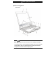
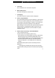
■ Chapter 1 getting to know the basics System At A glance Front View Note: Your computer may come with the 12.1 display in the wide 16:10 aspect ratio or in the standard 4:3 aspect ratio. If your computer comes with the wide 12.1 display, there is an extra pair of built-in loudspeakers located below the display panel.
■ Chapter 1 getting to know the basics 1. LCD Latch The LCD latches lock / unlock the LCD panel. 2. Built-in Microphone The built-in microphone records sound. 3. LCD Display The panel is where the system content is displayed. 4. Power / Suspend Button The power/suspend button turns the notebook on and off and it also acts as a system suspend key. Press momentarily to turn on the system. Press and hold for at least 3~4 seconds to turn off the system.
■ Chapter 1 getting to know the basics Note: The way the Power Cinema works is that when the key is pressed, the system boots to a Linux-based O/S and movie-player application in a separate hard drive partition. In case you have a brand new HDD or when you need to re-install O/S and Power Cinema, please go to Appendix C for installation instructions. 6.
■ Chapter 1 getting to know the basics 11. Touch Pad The touch pad is a built-in pointing device with functions similar to a mouse. 12. USB2.0 Port The Universal Serial Bus (USB2.0-compliant) port allows you to connect a wide variety of devices to your computer at a rate of up to 480 Mbps. This port conforms to the latest USB2.0 plug-and-play standards. 13. 4-in-1 Card Reader The 4-in-1 Card Reader supports SD Card, MS Card, MMC Card, and MS-Pro Card.
■ Chapter 1 getting to know the basics monitor or projector. 17. Built-in Stereo Speaker If your system comes with the 12.1-inch wide aspect ratio panel, there is an additional pair of speakers built-in.
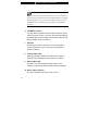
■ Chapter 1 getting to know the basics Rear View Warning:Do not place any heavy objects on the top of notebook. This may damage the display. 1. PC Card Slot ( Type II PCMCIA) and Card Eject Button The slot is where PC Card (Type II PCMCIA) is inserted. Press the eject button to release the PC Card. 2. Stereo Headphone / SPDIF-out Jack The stereo headphone jack (3.5-mm diameter) is where you connect the headphones or external speakers.
■ Chapter 1 getting to know the basics Note: In some models, the SPDIF-out feature may not be available. 3. Microphone Jack The microphone jack (3.5-mm diameter is where you connect a mircrophone. 4. Firewire/IEEEE1394 / 1394 Port This is a high-speed serial data port. You may connect any Fire-wire-ready device to this port. Note: In some models, the Firewire/1394 Port may not be available 5. USB2.0 Port The Universal Serial Bus (USB2.
■ Chapter 1 getting to know the basics 7. Modem Port This is where you plug the phone jack (RJ-11) for fax/modem functions. 8. Ethernet / LAN Port The port connects to a network hub via the RJ-45 cable and also conforms to 10/100Base-TX transmission protocol. 9. Kensington Lock Key Hole A Kensington-type security lock latches to this keyhole for anti-theft purpose. 10. Power Jack (DC-in) The DC-out jack of the AC Adapter connects here and powers the computer. 11.
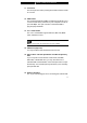
■ Chapter 1 getting to know the basics Bottom View 1. Ventilation Grill The fan grill is where air is exchanged to dissipate the internal heat. Do not block this airway completely. Note: Do not block the Fan Grill outlet. Place the machine on hard surface only. The bottom case may get very hot. 2. Battery Pack and Battery Latch The battery pack is a built-in power source for the notebook. Slide the battery latch to release the battery pack.
■ Chapter 1 getting to know the basics 3. USB Device (Optional) You may install the USB Thumb Drive into this slot. And make sure you put the latch in the locked position. Put the latch in the unlocked position before removing the module. 4.
■ Chapter 1 getting to know the basics You may install the optional wireless LAN module into this slot. 5. System Device Cover The system’s processor with cooler assembly, hard disk drive, and DDR memory module are located under the case cover. The system memory and HDD can be upgraded.
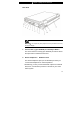
■ Chapter 1 getting to know the basics AC Adapter 1. DC-out Connector The DC-out connector docks to the power jack (DC-in) on the computer. 2. Adapter The adapter converts alternating current into constant DC voltage for the computer. 3. AC Plug The AC plug plugs to the AC wall outlet. Warning:Make sure you are using a standard 3-prong AC wall socket with a ground pin. If not, you may feel a slight tingling sensation on any of the computer’s metal parts such as the I/O ports.
■ Chapter 1 getting to know the basics LED Status The LED Status Indicator displays the operating status of your notebook. When a certain function is enabled, an LED will light up. The following section describes its indication. System Status Indicator LED Graphic Symbol Indication Green light indicates the WLAN module is active. Blinking green light indicates the notebook is in suspend mode Blinking orange light indicates the battery is being charged.
■ Chapter 1 getting to know the basics Keyboard Features Function Keys (Quick Keys) Graphic Symbol Action System Control Fn + F1 Enters Suspend Mode. Fn + F3 Turns of the battery warning beep off or on. Fn + F4 Changes Display Mode: LCD-only, CRT-only and LCD&CRT. Fn + F5 Turns Speaker Volume up. Fn + F6 Turns Speaker Volume down. Fn + F7 Increases Display Brightness. Fn + F8 Decreases Display Brightness. Fn+Num Lk Enables the embedded keypad to work in numeric mode.
■ Chapter 1 getting to know the basics Windows Keys Your keyboard also has two Windows keys: 1. Start Key This key allows you to pull up the Windows Start Menu at the bottom of the taskbar. 2. Application Menu Key This key brings up the popup menu for the application, similar to a click of the right mouse button. Embedded Numeric Keypad Press Fn+Num Lk to enable the embedded numeric keypad. The numbers are printed in upper right corner of a key, in a color different from the alphabets.
■ Chapter 1 getting to know the basics Touch Pad The built-in touch pad, which is a PS/2-compatible pointing device, senses movement on its surface. As you move your fingertip on the surface of the pad, the cursor responds accordingly. The following items teach you how to use the touch pad: 1. Move your finger across the touch pad to move the cursor. 2. Press buttons to select or execute functions. These two buttons are similar to the left and right buttons on a mouse.
■ Chapter 1 getting to know the basics Graphic Subsystem Your computer uses a high performance 14.1-inch active matrix TFT panel with high resolution and multi-million colors for comfortable viewing. The Intel Integrated GMA900 Extreme3 video graphics accelerator, which is Microsoft DirectX 9 compatible, performs graphic rendering at a lighting-fast speed. Adjusting the Display Brightness The notebook uses special key combinations, called hot keys, to control brightness.
■ Chapter 1 getting to know the basics Opening and Closing the Display Panel To open the display, push the LCD latch inwardly and lift up the lid. Then tilt it to a comfortable viewing position. To close the display cover, fold it down gently until the LCD latches click into place. Warning: To avoid damaging the display, do not slam it when closing. Do not place any object on top of the computer when the display is closed.
■ Chapter 1 getting to know the basics Audio Subsystem Your computer’s audio subsystem is Sound Blaster Pro-compatible. Adjusting the Volume Manually To increase the volume, press Fn+F5. To decrease the volume, press Fn+F6. Adjusting the Audio Volume in Windows 1. Click the speaker symbol in the task tray in Windows. 2. Drag the volume control bar up or down to adjust the volume. 3. To temporarily silence the speaker without changing the volume setting, click Mute.
■ Chapter 1 getting to know the basics Modem Your computer comes with a 56K V.92 internal fax/modem and a phone jack (RJ-11), which is located on the left side of your computer. Use a telephone cable to connect the computer to the telephone wall outlet. Connecting the Modem 1. Plug one end of the phone line into the modem port located on the rear side of the computer. (For EMI compliance, you need to clip the included EMI CORE to the phone line.) 2.
■ Chapter 1 getting to know the basics 2. Click on the pull-down menu and select the country where it is applicable. Click on OK to exit.
■ Chapter 1 getting to know the basics Ethernet Your computer is equipped with a 10/100Base-TX Fast Ethernet network adapter. Connect the active LAN cable to the RJ-45 LAN port located on the left side of the computer. This allows you to access and transmit data in the local area network. Connection to the network Use Unshielded Twisted Pair (UTP) Ethernet cable only. 1. Insert one end of the UTP cable into the network connector until the connector snaps securely into the receptacle. 2.
■ chapter 2 bios setup and security feature C H A P T E R ▼ T W O BIOS SETUP AND SECURITY FEATURE In this chapter, you will learn how to enter the BIOS Setup Menu and manipulate various hardware control settings. You will also learn how to use the built-in security features.
■ chapter 2 bios setup and security feature The Setup Utility is a hardware configuration program built into your computer’s BIOS (Basic Input/Output System). It runs and maintains a variety of hardware functions. It is a menu-driven software, which allows you to easily configure and change the settings. The BIOS contains manufacture’s default settings for the computer’s standard operations. However, there are occasions when you may be required to modify the default settings in the BIOS.
■ chapter 2 bios setup and security feature Entering the BIOS Setup Screen First turn on the power. When the BIOS performs the POST (Power-On Self Test), press F2 key quickly to activate the AMI BIOS Setup Utility. Note: You may need to press F2 key fairly quickly. Once the system begins to load Windows, you may have to retry by cycle-power on again Leaving the BIOS Setup Screen When you have finished modifying the BIOS settings, exit the BIOS. It takes a few seconds to record changes in the CMOS.
■ chapter 2 bios setup and security feature Modifying the BIOS Settings The AMIBIOS setup main menu is subdivided into sub-menus. Each menu item is described in this section. Main Setup Under this menu, you may change time/date and view basic processor and system memory information. Item Date Selections / Sub-menu N/A Time N/A Description Type in the current date, in MM/DD/YY format. Type in the current date, in HH:MM:SS format.
■ chapter 2 bios setup and security feature Item Selections / Sub-menu TouchPad Enabled Support Disabled Share Memory 32MB 64MB 128MB LCD Enabled AutoDimm Disabled Function Description Enable or disable the built-in touchpad. You may choose the amount of system memory to be used as video frame buffer. [Enabled]: The LCD backlight automatically decreases when the AC Adapter is unplugged from the wall. [Disabled]: This function is disabled.
■ chapter 2 bios setup and security feature ►Boot Device Priority Item 1st Boot Device Selections / Description Sub-menu Removable Dev. Set the type of device for the 1st drive Intel UNDI, PXE-2 BIOS attempts to boot from. If Intel UNDI, Hard Drive PXE-2 is selected, system will attempt to CD/DVD load boot sector from the Ethernet port. 2nd Boot Device Set the type of device for the 2nd drive BIOS attempts to boot from.
■ chapter 2 bios setup and security feature Security Setup ►Boot Settings Configuration Item Change Supervisor Password Change User Password Clear User Password Boot Sector Virus Protection Selections / Sub-menu N/A Description N/A Install or Change the Password N/A Install or Change the Password Disabled Enabled To enable or disable the boot sector protection. When Enabled, BIOS gives a warning when any program attempts to rewrite or delete the boot sector.
■ chapter 2 bios setup and security feature The passwords activate two different levels of protection: 1. System always asks for password every time it is powered on. 2. System asks for password only when you attempt to enter BIOS utility. The passwords are encrypted and stored in NVRAM. Make sure you write them down or memorize them. If you lost the passwords, the computer may need to be sent back to the factory or to an authorized service dealer to reset the passwords.
■ chapter 2 bios setup and security feature Power Setup Item Selections / Sub-menu Description Power Button Mode On/Off Suspend [On/Off]: When the power button is pressed, the system is turned off. [Suspend]: When the power button is pressed, the system enters the suspend mode. Note: The Suspend Mode selection in BIOS only applies to older Windows version (such as Windows 3.1 or Windows 95 or NT4) or non-Windows operating system.
■ chapter 3 battery power & power management C H A P T E R ▼ T H R E E BATTERY POWER & POWER MANAGEMENT In this chapter, you will learn the fundamentals of power management and how to use it to achieve longer battery life.
■ chapter 3 battery power & power management In this chapter, you will learn how to operate your notebook on battery power, how to handle and maintain the battery pack, and learn about the system’s power saving features. TFT display, central processor, hard disk drive are the major hardware subsystems that consume the most power. Power management deals how these key components should behave to conserve power.
■ chapter 3 battery power & power management Battery Low-Power Warning 1. Low Battery Warning Low battery condition occurs when battery power is reduced to 6%. The red battery status LED indicator blinks and the system beeps once every 16 seconds or so. 2. Very Low Battery Warning Very Low battery condition occurs at 3 % power remaining. The red battery status LED indicator blinks and the system beeps at 4-second interval.
■ chapter 3 battery power & power management Installing and Removing the Battery Pack To Remove the Battery Pack: 1. Place the notebook bottom-side up on a flat and secured surface. 2. Push the latch and pull the battery’s hard case away from the notebook.
■ chapter 3 battery power & power management To Install the Battery Pack: 1. Place the notebook bottom-side up on a flat and secured surface. 2. Carefully insert the battery pack into the battery compartment of the notebook. Charging the Battery and Charging Time To charge the battery, while the battery pack is in the notebook, plug the AC adapter into the notebook and an electrical outlet.
■ chapter 3 battery power & power management Checking the Battery Level You can check the remaining battery power in the Windows battery status indicator, which is located at the lower right-hand corner of the task bar. (If you do not see a battery or AC-in icon on the task tray, go to Power Options Properties box and click on the Advanced tab. Check off ``Always show icon on the task bar``.) Alternatively, you can access the power meter by clicking the Power Options icon in the Windows Control Panel.
■ chapter 3 battery power & power management Using Windows Power Options Windows Power Management provides basic power saving features. In the Windows Power Options Properties [Start > Settings > Control Panel > Power Options] dialogue box, you may enter time-out values for display and hard disk drive. Windows power manager saves power by turning off hard drive after 1 minute of inactivity, for example.
■ chapter 3 battery power & power management In this dialog box, you can manually set the LCD and hard drive’s time-out values in the Plugged in column and in the Running on batteries column. Lower time-out values will save more battery power. Note: Also consult Windows user guide for more information on how to use Windows power management functions. Note: Actual dialogue box shown above may appear slightly different.
■ chapter 3 battery power & power management Suspend Mode Standby Suspend The system automatically enters this mode after a period of inactivity, which is set in the Power Schemes dialog box. In Standby mode, hardware devices, such as display panel and hard disk, are turned off to conserve energy. Hibernate Suspend In this mode, all system data are saved in the hard disk before powering down.
■ chapter 3 battery power & power management Note: Do not install or remove the memory module when the system is in the suspend mode. Note: Actual dialogue box shown above may appear slightly different.
■ chapter 3 battery power & power management Power Button Action The notebook PC’s power button can be set to turn off the system or activate the suspend mode. Go to [Start > Settings > Control Panel > Power Options] and click on the Advanced tab. In the pull-down menu, select how you wish the power button to work as. Note: Actual dialogue box shown above may appear slightly different.
■ chapter 3 battery power & power management Low Battery Warning You can define when and how the system warns you of its battery-low condition. Go to the Alarms tab in the Power Options Properties box. If you wish to hear audible beeps, click on the Alarm Action button and put a check on Sound Alarm. Note: Consult Windows user guide for more information on how to use Windows power management functions. Note: Actual dialogue box shown above may appear slightly different.
■ chapter 3 battery power & power management Power Menu Quick Access Instead of making specific selections in the Power Options Properties box, you can quickly and easily specify which pre-set power saving function you desire by clicking on the Battery icon at the lower right-hand corner of the task bar. (If you do not see a battery or AC-in icon, go to Power Options Properties box and click on the Advanced tab. Check off ``Always show icon on the task bar``.
■ chapter 4 upgrading your computer C H A P T E R ▼ F O U R UPGRADING YOUR COMPUTER In this chapter, you will learn how to upgrade the DRAM, hard disk drive, and to install the optional wireless LAN mini PCI. Warning: We strongly recommend you sending your notebook back to your dealer or agent for the specification upgrading. When you upgrade your system, please turn off the power, disconnect the LAN and Modem cable first for your safety.
■ chapter 4 upgrading your computer Upgrading the Hard Disk Drive Replacing the original drive with one of larger capacity can increase the hard drive capacity of your computer. The computer uses a 9.5 mm (height), 2.5-inch Ultra ATA-66 / 100 / 133 type hard disk. Be sure to make a backup copy of all your data before attempting this operation. Warning: Hard drive upgrade is a delicate process. Please observe the following instructions carefully or have a qualified technician install it for you.
■ chapter 4 upgrading your computer Upgrading the Hard Disk Drive To replace the hard disk drive, do the following: 1. Turn OFF the computer. Unhook the AC cord and all cables/devices attached to the notebook. Remove the battery back. 2. Place your hand on a large metal object momentarily to discharge any static electricity. 3. Locate and remove Screw A. 4. Remove HDD Cover. 5.
■ chapter 4 upgrading your computer 6. Life the thermal module away from the bay and carefully separate the module from the thermal connector. 7. 8. Remove 3 Screw B’s. Life the HDD module away from the bay and carefully separate the module from the HDD connector. HDD Connector 9. 10. 4-4 Locate and remove 4 Screw C’s from the HDD module. Remove the metal case.
■ chapter 4 upgrading your computer 11. 12. 13. Re-attach the metal cover to the new hard drive and tighten 4 Screw C’s. Note the green PC board of the hard disk drive is facing against the metal case. Re-attach the HDD module to the HDD connector. Put the HDD cover back and re-attach Screw A. Congratulations! You have now completed the hard drive upgrade.
■ chapter 4 upgrading your computer Upgrading the System Memory Many applications will generally run faster when the computer’s dynamic memory capacity is increased. The computer provides two DDR memory sockets, located underneath the System Device Cover. You can increase the amount of memory by replacing the existing one with a dual inline memory module (commonly known as SO-DIMM) of a higher capacity. The SO-DIMM can be 128MB, 256MB, or 512MB in capacity.
■ chapter 4 upgrading your computer Installing a memory module (DIMM) into the system To install the DIMM, do the following: 1. Turn OFF the computer. Unhook the AC cord and all cables/devices attached to the notebook. Remove the battery back. 2. Place your hand on a large metal object momentarily to discharge any static electricity. Place the notebook on a flat surface and fully close the LCD lid. 3. Locate and remove 7 Screw C’s on the System Device Cover. 4. Remove the System Device Cover.
■ chapter 4 upgrading your computer 5. If you need to remove an old DIMM from the socket, press out on the latches located on both edges of the socket at the same time. The DIMM should pop up to an angle of 30 degree (see diagram below). Pull the DIMM module out of the memory socket. Store away the DIMM for the future use. 6. Install the new DIMM module into the memory socket. The DIMM will only fit in one orientation.
■ chapter 4 upgrading your computer angle of approximately 30 degrees into the empty memory socket. Then press it firmly so that the contact edge is driven into the receiving socket. Notch 7. Pivot the DIMM until the latches on both sides of the socket snap into place. Note: Notice the notch on the DIMM. The notches should fit nicely with the socket. 8. Put the System Device Cover back and tighten 7 Screw C’s. Congratulations! You have just completed the memory upgrade.
■ chapter 5 trouble shooting C H A P T E R ▼ F I V E TROUBLE SHOOTING In this chapter, you will learn how to solve common hardware and software problems.
■ chapter 5 trouble shooting Your computer has been fully tested and complies with the system specifications before shipping. However, incorrect operations and/or mishandling may cause problems. This chapter provides a reference for identifying and correcting common hardware and software problems that you may encounter. When you encounter a problem, you should first try to go through the recommendations in this chapter.
■ chapter 5 trouble shooting hardware devices in the BIOS Setup utility. A faulty setting may cause the system to misbehave. If you are not sure of the changes you made, try to restore all the settings to factory defaults. Be sure all the device drivers are installed properly. For example, without the audio driver properly installed, the speakers and microphone will not work.
■ chapter 5 trouble shooting Audio Problems No speaker output Turn up the volume dial located at the right edge of the computer. See Chapter 1 for its location. Software volume control is turned down in Microsoft Sound System or is muted. Double-click the speaker icon on the lower right corner of the taskbar to see if the speaker has been muted or turned down all the way. Most audio problems are software-related. If your computer worked before, chances are software may have been set incorrectly.
■ chapter 5 trouble shooting Hard Disk Problems The hard disk drive does not work or is not recognizable If you had just performed a hard disk upgrade, make sure the hard drive connector is not loose and the hard disk drive is also correctly seated. Remove it and reinsert it firmly, and restart your PC. (Refer to Chapter 4 for details.) The new HDD may need to be partitioned and reformatted. O/S and drivers will need to be re-installed as well. Check the hard disk indicator LED.
■ chapter 5 trouble shooting for instructions on decreasing the cache size or on removing temporary Internet files. Empty the Recycle Bin to create more disk space. When you delete files, Windows saves them to the Recycle Bin. The hard disk takes longer to read a file If you have been using the drive for a period, the files may be fragmented. Go to [Start > Programs > Accessories > System Tools > Disk Defragmenter] to perform a disk defragmentation. This operation may take a while.
■ chapter 5 trouble shooting Optical Drive Problems The optical drive does not work Try rebooting the system. The disk is damaged or files are not readable. After you have inserted a CD-ROM disk, it may take a moment before you can access its content. The drive dose not read any disks The CD may not be properly seated in the tray. Make sure the disk is firmly seated onto the spindle. The disk is damaged or not readable. The disk cannot be ejected Normally, it takes a few seconds to eject the disk.
■ chapter 5 trouble shooting Display Problems The display panel is blank when the system is turned on Make sure the computer is not in the Standby or Hibernate suspend modes. The display is turned off to conserve energy in these modes. The screen is difficult to read The display resolution should at least be set to at least1024x768 for optimal viewing. 1. Go to [Start > Settings > Control Panel] and double-click the Display icon. 2.
■ chapter 5 trouble shooting Keyboard and Mouse Problems The built-in touch pad performs erratically Make sure there is no excess perspiration or humidity on your hand when using the touch pad. Keep the surface of the touch pad clean and dry. Do not rest your palm or wrist on the surface of the touch pad while typing or using the touch pad. The built-in keyboard accepts no input If you are connecting an external keyboard to the system, the built-in keyboard may not work. Try restarting the system.
■ chapter 5 trouble shooting CMOS Battery Problem A message “CMOS Checksum Failure” displays during the booting process or the time (clock) resets when booting Try to reboot the system. If the message “CMOS Checksum Failure” appears during the booting procedure even after rebooting, it may indicate failure of the CMOS battery. If so, you need to replace the battery. This battery normally lasts two to five years. The battery is of type CR2032 (3V). You may replace it by yourself.
■ chapter 5 trouble shooting Memory Problems The POST does not show an increased memory capacity when you have already installed additional memory Certain brands of memory module may not be compatible with your system. You should ask your vendor for a list of compatible DIMM. The memory module may not be installed properly. Go back to Chapter 4 to review the details of this operation. The memory module may be defective.
■ chapter 5 trouble shooting Modem Problems The built-in modem does not respond Make sure the modem driver is loaded properly. Go to [Start > Settings > Control Panel > Phone and Modem Options] and go to Modems tab. Make sure SmartLink 56K Voice Modem or Uniwill V.92 Modem is listed. Otherwise, click the Add button to add the modem drive, which is located in the factory CD-ROM (or floppy diskette).
■ chapter 5 trouble shooting Network Adapter / Ethernet Problems The Ethernet adapter does not work Go to [Start > Settings > Control Panel > System > Hardware > Device Manager]. Double-click on Network Adapters and check if Realtek RTL8139/810x Family Fast Ethernet NIC appears as one of the adapters. If it does not exist, Windows has not detected the Realtek RTL8139/810x Family Fast Ethernet NIC or the device driver has not been installed properly.
■ chapter 5 trouble shooting PC Card / PCMCIA Problems Note: Some system may not have the PC Card Slot option. PC Cards do not functionMake sure you have properly installed the driver for the card. Consult the card’s manual or contact the vendor for trouble-shooting. The PC card cannot be recognized Windows NT4.0 does not support PCMCIA (PC Card) function. You may need an external program for this. Make sure the card is fully inserted; the outer end of the card should be even with the edge of the computer.
■ chapter 5 trouble shooting Performance Problems The computer becomes hot In a 35oC environment, the certain areas of the computer’s back case are expected to reach 50 degrees. Make sure the air vents are not blocked. If the fan does not seem to be working at high temperature (50 degrees Celsius and up), contact the service center.
■ chapter 5 trouble shooting Firewire (IEEE1394) and USB2.0 Problems The USB device does not work Windows NT 4.0 does not support USB protocols Check the settings in the Windows Control Panel. Make sure you have installed the necessary device drivers. Contact the device vendor for additional support. The IEEE1394 port does not work Go to [Start > Settings > Control Panel > System > Hardware > Device Manager]. You should see an entry which reads “Texas Instrument OHCI Compliant IEEE 1394 Host Controllers”.
■ appendix A product specification A P P E N D I X ▼ A PRODUCT SPECIFICATION A-1
■ appendix A product specification Processor Core Logic ▼ Processor and Core Logic Intel Pentium-M Dothan CPU 1.4 to 2.0 400 MHz FSB 2M L2 Cache Intel Pentium-M Dothan CPU 1.6 to 2.13 533 MHz FSB 2M L2 Cache Intel Celeron M, Operating to 1.70 GHz, 400MHz FSB, 1MB L2 cache Intel 915GM(Alviso)+ICH6-M(FW82802FBW) chipset with graphic, audio, modem, and USB2.0 controllers integrated 533Mhz(Pentium M),400(celeron M) Front side Bus DDR2 interface.
■ appendix A product specification Chipset Audio Codec Sound Capabilities Chipset Transmission Rate Module Transmission Protocol Chipset PnP Function Flow Control Speed Selection Other Features ▼ Audio VT1612A chipset DirectSound 3D, EAX 1.0 & 2.0 compatible A3D, I3DL2 compatible AC97 V2.2 compatible 2 or 4 Stereo Speakers ▼ Modem Intel (ICH6M) integrated Modem Controller with MDC card, AC97 V2.2 Modem support V.92 / V.90 / K56flex for download data speed up to 56Kbps. V.34, V.17, V.
■ appendix A product specification Chipset Capabilities Hard Drive Combo Drive DVD±R/±RW or DVD-Dual or DVD-Multi Standards Keyboard Touch pad Chipset PC Card 4-in-1 Card Reader Format Support A-4 ▼ Firewire IEEE1394(a) TI TSB43AB22A IEEE1394 OHCI Host Controller and Up to 400 Mbps Expandable up to 63 devices in chains ▼ Storage 2.5-inch format hard disk drive 5.25-inch format (12.7mm height) fixed module (Optional Purchase) 5.25-inch format (12.
■ appendix A product specification Mic-In Port Audio-Out / SPDIF Firewire USB2.0 Port Ethernet Modem S-Video Power-In VGA Port Card Reader PC Card Slot ▼ Ports and Connectors One Microphone-in jack One Headphone / SPDIF jack One Firewire (IEEE1394) host connector Two USB2.
■ appendix A product specification Power Management Security Other Features ▼ BIOS AMI PnP BIOS Power On Self Test DRAM auto-detection, auto-sizing L2 Cache auto-detection Hard disk type auto-detection APM 1.2 (Advanced Power Management) & ACPI 2.
■ appendix B agency regulatory notices A P P E N D I X ▼ B AGENCY REGULATORY NOTICES B-1
■ appendix B agency regulatory notices Federal Communications Commission Notice This equipment has been tested and found to comply with the limits for a Class B digital device, pursuant to Part 15 of the FCC Rules. These limits are designed to provide reasonable protection against harmful interference in a residential installation.
■ appendix B agency regulatory notices 1) The transmitter module may not be co-located with any other transmitter or antenna. As long as condition above is met, further transmitter test will not be required. However, the OEM integrator is still responsible for testing their end-product for any additional compliance requirements required with this module installed (for Notebook).
■ appendix B agency regulatory notices Declaration of Conformity This device complies with Part 15( CLASS B)/68 the FCC Rules. Operation is subject to the following two conditions: (1) this device may not cause harmful interference, and (2) this device must accept any interference received, including interference that may cause undesired operation.
■ appendix B agency regulatory notices Power Cord Requirement The power cord supplied with the AC adapter should match the plug and voltage requirements for your local area. Regulatory approval for the AC adapter has been obtained using the power cord for the local area. However, if you travel to a different area and need to connect to a different outlet or voltage, you should use one of the power cords listed below.
■ appendix B agency regulatory notices CCC (China) PSB (Singapore) PSE (Japan) BSMI (Taiwan) B (Polish) VDE (Germany) SASO (Saudi Arabia) The flexible cord must be of a HAR (harmonized) type HO5VV-F 3-conductor cord with a minimum conductor size of 0.03 square inches. The minimum specification for the flexible cord for Class II product 2 are: (1) 2X0.75 mm conductors, (2) 2-conductor cord. The cord set must have a current capacity of at least 10 A and a nominal voltage rating of 125 / 250 VAC.
■ appendix B agency regulatory notices To obtain a replacement battery, contact your local dealer. Do not expose the battery pack to high storage temperatures (above 60℃, 140℉). When discarding a battery pack, contact your local waste disposal provider regarding local restrictions on the disposal or recycling of batteries. Use only supplied AC Adapter for charging. CAUTION: Danger of explosion if battery is incorrectly replaced. Replace only with same or equivalent type recommended by the manufacturer.
■ appendix B agency regulatory notices Lithium battery warning / Bridge battery warning This computer contains a lithium battery to power the clock and calendar circuitry. CAUTION: Danger of explosion if battery is replaced incorrectly. Replace only with the same or equivalent type recommended by the manufacturer. Discard used batteries according to the manufacturer’s instructions. ATTENTION: Il y a danger d’xplosion s’il y a remplacement incorrect de la batterie.
Notice The information in this user’s manual is subject to change without notice. THE MANUFACTURER OR RESELLER SHALL NOT BE LIABLE FOR ERRORS OR OMISSIONS CONTAINED IN THIS MANUAL AND SHALL NOT BE LIABLE FOR ANY CONSEQUENTIAL DAMAGES, WHICH MAY RESULT FROM THE PERFORMANCE OR USE OF THIS MANUAL. The information in this user’s manual is protected by copyright laws. No part of this manual may be photocopied or reproduced in any form without prior written authorization from the copyright owners.
TABLE OF CONTENTS PREFACE Symbols and Conventions Protecting Your Computer - Avoid Abusive Handling and Adverse Environment Chapter Summaries 1.
Main Setup (2-4) Advance Setup (2-4,5) Boot Setup (2-5,6) Security Setup (2-7,8) Power Setup (2-9) Exit Setup (2-9) 3.
PC Card / PCMCIA Problems (5-14) Performance Problems (5-15) Firewire (IEEE1394) and USB2.
Preface Using This Manual This User’s Manual contains general information about the hardware and software setup, troubleshooting, and technical specifications of the notebook computer. Symbols and Conventions The following conventions and symbols are used in this manual: When keys are to be pressed at the same time, a plus (+) symbol is used. For instance, Fn+F7 means holding Fn and F7 keys at the same time. When a series of clicking actions is needed in Windows O/S, [ ] and > symbols are used.
Protecting Your Computer - Avoid Abusive Handling and Adverse Environment Follow the advice below will help ensure that you get the most out of your Investment. Your computer will serve you well if you take good care of it. Do not expose the computer to direct sunlight or place it near sources of heat. Do not subject it to temperatures below 0oC (32oF) or above 30oC (86oF). Do not expose the computer to magnetic fields. Do not expose the computer to moisture or rain.
Keep the adapter away from children. The total ampere ratings of the equipment plugged in should not exceed the ampere rating of the cord if you are using an extension cord. The total current rating of all equipment plugged into a single wall outlet should not exceed the fuse rating. Do not connect other AC adapter to your notebook. This Notebook uses exclusively the AC adapter: Manufacture: LITE-ON ELECTRONICS, INC.; LI SHIN INTERNATIONAL ENTERPRISE CORP, ELECTRICITY POWER SOURCE(EPS) INC.
Chapter Summaries The following is a summary of the available chapters and appendices in this manual. Chapter 1: Getting to Know the Basics In this chapter, you will learn the basic operations and features of your computer. It gives you a general understanding of the components of your computer. Chapter 2: BIOS Setup / Security In this chapter, you will learn how to change various firmware settings and what the settings mean.