
Use and Care Guide


-3-
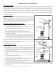
1. Uncrate and/or unpack the heater, removing all packing material, being careful not to dispose of the Parts
Bag.
2. Remove the following contents:
A. (4) Legs with nut and bolt package
B. (1) Lid with (1) Lid Lifter
C. (1) Shaker Grate
D. (1) Ash Door with (1) Slide Draft
E. (1) Feed Door
3. Carefully lay the stove on its side, preferably on a soft surface. Note: Cardboard shipping carton placed
at works well for this application.
4. Securely attach all four (4) legs to lower chamber using nut and bolt package.
5. Carefully return stove to upright position and place it in desired location.
6. Place lid in position on top plate.
7. Position ash door with slide draft on front of lower chamber.
8. Place shaker grate in lower chamber.
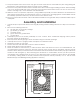
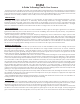
9. Place the heater on solid masonry, or solid concrete. When the heater is used on a combustible oor, use
an Underwriters Listed oor protector. The oor protector must comply with UL Standards. The base should
extend at least 18" beyond the door side of the heater and should extend under the ue pipe (if it is elbowed
towards a wall, see gure 4). After observing the clearances to combustibles, locate your oor protector
accordingly and carefully place the stove in your selected location. Install stove pipe, elbows and thimble
as necessary, utilizing either a recently cleaned and inspected masonry chimney or a UL 103 HT Listed
Residential Type and Building Heating Appliance Chimney.
11. The special paints used on this stove may give off some smoke and an odor while they are curing during the
rst few res. Paint discoloration will occur if the stove is overred.
12. This stove has a painted surface which is durable but it will not stand rough handling or abuse. When installing
your stove, please handle with care. Clean with soap and warm water when stove is not hot. Do not use any
acids or scouring soap, as the will wear and dull the nish.
13. While the stove is in operation, all persons, young children especially, should be alerted to the hazards from
high surface temperatures and should keep away to avoid burns or clothing ignition. Small children should
be carefully supervised when they are in the same room with the stove.
14. Keep stove area clear and free of all combustible materials such as gasoline and/or other ammable vapors
and liquids.
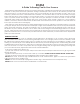
Assembly and Installation
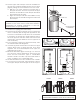
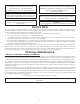
FIG. 6
FLUE CONNECTION-NON-COMBUSTIBLE WALL
FLOOR PROTECTOR
PIPE
BAROMETRIC
DRAFT REGULATOR
ELBOW
PIPE
COLLAR
THIMBLE
NON-COMBUSTIBLE WALL
FIG. 7
CHIMNEY CAP MANDATORY
3 FT. MIN.
2 FT. MIN
10 FT.
PIPE REDUCER
11 FT. MINIMUM
PIPE
FLOOR PROTECTOR
BAROMETRIC
DRAFT REGULATOR
NON-COMBUSTIBLE
CONSTRUCTION IN
ACCORDANCE WITH
NFPA 211
FLOOR
PROTECTOR
(60"
MIN
.)
FIG. 4
FLOOR
PROTECTOR
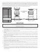
10-1/4
36"
18"
FIGURE 2 FIGURE 3
42"
36"
39-1/2"
14-1/2"
FLOOR
PROTECTOR
NON- COMBUSTIBLE
CONSTRUCTION IN
ACCORDANCE WITH
NFPA 211
DASHED LINES
SHOW STRAIGHT
OUT CHIMNEY
CONNECTOR
36"
54"
36"
HEATER/FLOOR PROTECTOR LOCATION