
Use and Care Guide


-4-
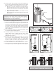
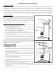
10. The ue pipe draft damper must be installed into
the top end of the rst straight section of stove pipe
(gure1) exiting the stove before the stove is used.
a. Drill two 1/4” holes centered on either side of
the pipe section 6” from the top end of the pipe
Remove the handle from the damper then slide
the damper into the pipe.
b. Align the damper with the holes drilled in step
8a and insert the handle through the holes and
the damper.
11. Attach stove piping (see instructions).
12. The stove must have its own ue. Do not connect this
unit to a chimney ue serving other appliances. This
stove has a circular ue outlet and uses a standard
6" stovepipe. To attach pipe, simply slide the end of
the stove pipe into the ue outlet and secure with
metal screw. Connect balance of stove pipe into a
class A chimney
13. If your chimney continues to draft excessively, then
use a Barometric Draft Regulator.
14. Use three (3) sheet metal screws in each stove pipe
and/or elbow joint to rmly hold the stove pipe
together. Use 6" round black/blue stove pipe, not
galvanized stove pipe .
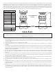
15. Recheck illustrations gure 2 through 7 to be sure
you have the proper clearances shown from the
stove and the connector pipe to combustible
surfaces. NOTE: If a wall is only faced with brick or
stone, consider it as a combustible wall.
16. DO NOT install this stove in a mobile home or trailer.
17. If you have too much draft, then install a 6" cast iron
stove pipe damper in the rst joint of the stove pipe.
CAUTION: KEEP FURNISHINGS AND OTHER
COMBUSTIBLE MATERIALS AWAY FROM THE HEATER.
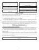
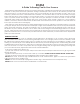
CORRECT WRONG WRONG
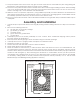
Stovepipe/Flue Connections
FIG. 5
MINIMUM CLEARANCE TO COMBUSTIBLE WALLS
FIG. 6
FLUE CONNECTION-NON-COMBUSTIBLE WALL
FLOOR PROTECTOR
PIPE
BAROMETRIC
DRAFT REGULATOR
ELBOW
PIPE
COLLAR
THIMBLE
NON-COMBUSTIBLE WALL
FIG. 7
CHIMNEY CAP MANDATORY
3 FT. MIN.
2 FT. MIN
10 FT.
PIPE REDUCER
11 FT. MINIMUM
PIPE
FLOOR PROTECTOR
BAROMETRIC
DRAFT REGULATOR
NON-COMBUSTIBLE
CONSTRUCTION IN
ACCORDANCE WITH
NFPA 211
FLOOR
PROTECTOR
(60" MIN.)
FIG. 4
FLOOR
PROTECTOR
10-1/4
36"
18"
FIGURE 2 FIGURE 3
42"
36"
39-1/2"
14-1/2"
FLOOR
PROTECTOR
NON- COMBUSTIBLE
CONSTRUCTION IN
ACCORDANCE WITH
NFPA 211
DASHED LINES
SHOW STRAIGHT
OUT CHIMNEY
CONNECTOR
36"
54"
36"
6"/15.25 cm
Draft Damper
Installation
NOTE: This damper is necessary for the proper
operation of the stove and to meet EPA emissions
requirements for heating appliances. It must be
installed before use (No exceptions)