
Use and Care Guide


-5-
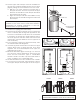
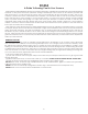
MASONRY CHIMNEY
The masonry chimney must comply with UL codes. Before using an existing masonry chimney, clean the chimney
and inspect the ue liner to be sure it is safe to use. Make repairs before attaching the heater. See gure 5, the
connector pipe and ttings you will need to connect directly to a masonry chimney are shown. If the connector
pipe must go through a combustible wall before entering the masonry chimney, consult a qualied mason or
chimney dealer. The installation must conform to local re codes, and NFPA 211. Do not connect this heater into
the same chimney ue as the replace or ue from another heater. The chimney used for a heater must not be
used to ventilate the cellar or basement. If there is a cleanout opening at the base of the chimney, close it tightly.
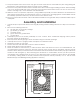
UL LISTED CHIMNEY
Carefully follow chimney manufacturer's instructions. Use only listed
type HT per UL 103, 6-in diameter black or blued chimney connector,
minimum 24 gauge steel. If your chimney starts at the ceiling (Figure
7), you will need enough 6" pipe to reach the ceiling. The top of the
chimney must be at least 3 feet above the roof and be at least 2 feet
higher than any point of the roof within 10 feet (Figure 7)
RULES FOR CONNECTOR PIPE INSTALLATION
1. The pipe should be rmly attached to the collar top with 3 screws
and sealed with furnace cement.
2. Slope any horizontal pipe upward toward the chimney at least
1/4" inch for each foot of horizontal run.
3. You must have at least 18" inches clearance between any
horizontal piping and the ceiling (gure 3).
4. The pipe cannot extend into the chimney ue (gure 5).
5. Seal each connector pipe joint with furnace cement. Also seal
the pipe at the chimney.
6. Use 3 sheet metal screws at each joint to make the piping rigid.
7. It is recommended that no more than two (2) 90 degree bends
be used in the stove pipe installation as more than two (2) may
decrease the amount of draw and possibly cause smoke spillage.
NOTE: The chimney connector shall not pass through an attic, roof
space, oor, ceiling, or similar concealed space. Where passage
through a wall or partition of combustible construction is desired, the
installation must conform with NFPA 211.
OPERATION OF THE STOVE
1. Fully open slide draft on ash door and keep spin damper on feed
door closed.
2. Burn coal only. Use wood for coal ignition purposes only. Build six
(6) small res upon initial ring. Light wood using paper, twigs, etc.
3. After the re has been started and is burning satisfactorily, close
slide draft almost all the way.
4. Open/adjust spin draft on feed door to allow additional air into
the stove (on top of the re). This will allow a more efcient burn
cycle.
5. Never build extremely large res in this type stove as damage to
the stove or smoking may result.
6. DO NOT touch the stove after ring
7. Never over re this stove by building excessively hot res as a
house/building re may result.
8. Inspect stove pipe every 90 days. Replace immediately if stove
pipe is rusting or leaking smoke into the room.
9. This is a cast iron stove. It does not have welded seams. From
time to time you may have to"tune-up" the stove by relling and/or replacing the stove cement or mortar
along the seams.
10. If stove begins to glow or turn red, you are over ring.
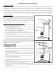
FIG. 6
FLUE CONNECTION-NON-COMBUSTIBLE WALL
FLOOR PROTECTOR
PIPE
BAROMETRIC
DRAFT REGULATOR
ELBOW
PIPE
COLLAR
THIMBLE
NON-COMBUSTIBLE WALL
FIG. 7
CHIMNEY CAP MANDATORY
3 FT. MIN.
2 FT. MIN
10 FT.
PIPE REDUCER
11 FT. MINIMUM
PIPE
FLOOR PROTECTOR
BAROMETRIC
DRAFT REGULATOR
NON-COMBUSTIBLE
CONSTRUCTION IN
ACCORDANCE WITH
NFPA 211
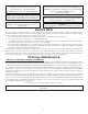
FLOOR
PROTECTOR
(60"
MIN
.)
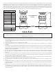
FIG. 4
FLOOR
PROTECTOR
10-1/4
36"
18"
FIGURE 2 FIGURE 3
42"
36"
39-1/2"
14-1/2"
FLOOR
PROTECTOR
NON- COMBUSTIBLE
CONSTRUCTION IN
ACCORDANCE WITH
NFPA 211
DASHED LINES
SHOW STRAIGHT
OUT CHIMNEY
CONNECTOR
36"
54"
36"
Chimney Connection