Owner’s Operation and Instruction Manual MODEL: 2500(L)(LN) SAVE THESE INSTRUCTIONS THIS MANUAL WILL HELP YOU TO OBTAIN EFFICIENT, DEPENDABLE SERVICE FROM THE HEATER, AND ENABLE YOU TO ORDER REPAIR PARTS CORRECTLY. KEEP IN A SAFE PLACE FOR FUTURE REFERENCE. CAUTION! Please read this entire manual before you install or use your new room heater. Failure to follow instructions may result in property damage, bodily injury, or even death.
CONGRATULATIONS! You’ve purchased a heater from North America’s oldest manufacturer of wood burning products. By heating with wood you’re helping to CONSERVE ENERGY! Wood is our only Renewable Energy Resource. Please do your part to preserve our wood supply. Plant at least one tree each year. Future generations will thank you. The instructions pertaining to the installation of your wood stove comply with UL-1482 and ULC-S627 standards.
TOOLS AND MATERIALS NEEDED FOR INSTALLATION You will need a drill with a 1/8” bit to install sheet metal screws into connector pipe. A 5/16” socket/wrench or screw driver to install pedestal trim, room air deflector, and blower assembly described below. A 1/2” socket/ wrench to install flue collar. A non-combustible floor protector as specified in this manual. All chimney and chimney connector components required for your particular chimney installation. For mobile homes, see page 13.
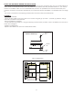
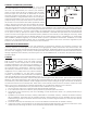
ASSEMBLY INSTRUCTIONS Blower Assembly THE BLOWER ASSEMBLY MUST BE DISCONNECTED FROM THE SOURCE OF ELECTRICAL SUPPLY BEFORE ATTEMPTING THE INSTALLATION. THE BLOWER ASSEMBLY IS INTENDED FOR USE ONLY WITH A STOVE THAT IS MARKED TO INDICATE SUCH USE. DO NOT ROUTE THE SUPPLY CORD NEAR OR ACROSS HOT SURFACES! Step 1. Fix the assembly to the back of the stove with the four screws provided. PEDESTAL TRIM ASSEMBLY Attach trim piece to the pedestal base at the location shown using the screws provided.
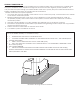
FLOOR PROTECTOR Your wood stove should be placed on a 1 inch, non-combustible surface with a k factor of 0.84. For multiple layers, add R-values of each layer to determine the overall R-value. The R value for the required board is 1.2.
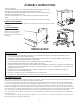
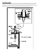
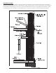
CHIMNEY CONNECTOR (STOVE PIPE) Your chimney connector and chimney must have the same diameter as the stove outlet (6”). If this is not the case, we recommend you contact your dealer in order to insure there will be no problem with the draft. The stove pipe must be made of aluminized or cold roll steel with a minimum thickness of 0.021” or 0.53 mm. It is strictly forbidden to use galvanized steel. Your smoke pipe should be assembled in such a way that the male section (crimped end) of the pipe faces down.
FACTORY BUILT CHIMNEY When a metal prefabricated chimney is used, the manufacturer’s installation instructions must be followed. You must also purchase (from the same manufacturer) and install the ceiling support package or wall passthrough and “T” section package, firestops (where needed), insulation shield, roof flashing, chimney cap, etc. Maintain proper clearance to the structure as recommended by the manufacturer.
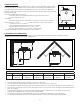
MASONRY CHIMNEY Ensure that a masonry chimney meets the minimum standards of the National Fire Protection Association (NFPA) by having it inspected by a professional. Make sure there are no cracks, loose mortar or other signs of deterioration and blockage. Have the chimney cleaned before the stove is installed and operated. When connecting the stove through a combustible wall to a masonry chimney, special methods are needed.
COMBUSTIBLE WALL CHIMNEY CONNECTOR PASS-THROUGHS Method A. 12” (304.8 mm) Clearance to Combustible Wall Member: Using a minimum thickness 3.5” (89 mm) brick and a 5/8” (15.9 mm) minimum wall thickness clay liner, construct a wall pass-through. The clay liner must conform to ASTM C315 (Standard Specification for Clay Fire Linings) or its equivalent. Keep a minimum of 12” (304.8 mm) of brick masonry between the clay liner and wall combustibles.
OUTSIDE COMBUSTION AIR Your wood stove is approved to be installed with an outside air intake which is necessary for a mobile home. This type of installation is also required in air tight houses and houses with negative pressure problems. You can purchase this option through your heater dealer. Make sure to specify the part number mentioned in this booklet. Installation instructions are supplied with the air intake kit. Outside combustion air may be required if : 1.
WOODSTOVE UTILIZATION This heater is designed to burn natural wood only. Higher efficiencies and lower emissions generally result when burning air dried seasoned hardwoods, as compared to softwoods or to green or freshly cut hardwoods. DO NOT BURN: 1. Garbage; 10. Salt water driftwood or other previously salt water 2. Lawn clippings or yard waste; saturated materials; 3. Materials containing rubber, including tires; 11. Unseasoned wood; or 4. Materials containing plastic; 12.
It is EXTREMELY IMPORTANT that you use DRY WOOD only in your wood stove. The wood should have dried for 9 to 15 months, such that the humidity content (in weight) is reduced below 20% of the weight of the log. It is very important to keep in mind that even if the wood has been cut for one, two or even more years, it is not necessarily dry, if it has been stored in poor conditions. Under extreme conditions it may rot instead of drying.
When you have achieved a good bed of hot embers, we recommend the following burn procedures: Burn Rate Adjust Damper from fully closed Burn Time Blower Speed Low 1/32” (1mm) @ 30 minutes Low Medium - Low 1/16” (1.5mm) @ 30 minutes Low Medium - High 5/16” (8mm) @ 30 minutes Low High approx. 3” (76mm) all minutes High CAUTION: Never alter the damper slide or the adjustment range to increase firing for any reason. Doing so could result in heater damage and will void your warranty.
RELOADING Once you have obtained a good bed of embers, you should reload the unit. In order to do so, open the air controls to maximum a few seconds prior to opening the stove’s door. Then proceed by opening the door very slowly; open it one or two inches for 5 to 10 seconds, before opening it completely to increase the draft and thus eliminate the smoke which is stagnant in a state of slow combustion in the stove. Then bring the red embers to the front of the stove and reload the unit.
SMOKE AND CO MONITORS Burning wood naturally produces smoke and carbon monoxide(CO) emissions. CO is a poisonous gas when exposed to elevated concentrations for extended periods of time. While the modern combustion systems in heaters drastically reduce the amount of CO emitted out the chimney, exposure to the gases in closed or confined areas can be dangerous. Make sure you stove gaskets and chimney joints are in good working order and sealing properly to prevent unintended exposure.
REPAIR PARTS In order to maintain warranty, components must be replaced using original manufacturers parts purchased through your dealer or directly from the appliance manufacturer. Use of third party components will void the warranty. 1 2 5 4 3 6 17 16 7 8 15 14 9 13 12 10 11 Key 1 2 3 4 5 6 7 8 Part No.
REPAIR PARTS 7 6 8 5 4 3 9 2 Key 1 2 3 1 4 5 6 7 8 9 Part No. Description 891135 Spring Handle - Lg 25692 83506 25491 40770 88066 88087 891131 25464 25465 Handle 3/8 X 1-1/4 Roll Pin Feed Door Feed Door (for LN) Gasket, 5/8 Rope (Ld2 .625 G) Glass Gasket (1 X 3/16) Ceramic Glass Retainer, Top Glass Retainer, Bottom Glass Qty. 1 1 1 1 1 4.6 ft 4 ft 1 1 1 8 Key Part No. 1 2 3 4 5 6 7 8 891414 89066 24103 40561 891530 86645 86643 88138 Description Qty.
SERVICE RECORD It is recommended that your heating system is serviced regularly and that the appropriate Service Interval Record is completed. Service Provider: Before completing the appropriate Service Record below, please ensure you have carried out the service as described in the manufacturer’s instructions. Always use the manufacturer's specified spare part when replacement is necessary.
Limited Warranty The operation of this unit in a manner inconsistent with the owner’s manual will void the warranty and is also against federal regulations. United States Stove Company warrants this product to be free from defects in material and workmanship, to the original retail purchaser only, for the time period identified below, measured from the date of the initial purchase as evidenced on an invoice, cancelled check, sales receipt, etc.
HOW TO ORDER REPAIR PARTS / COMMENT COMMANDER DES PIÈCES DÉTACHÉES This manual will help you obtain efficient, dependable service from your heater, and enable you to order repair parts correctly. Keep this manual in a safe place for future reference. When writing, always give the full model number which is on the nameplate attached to the heater.
Garantie limitée L’utilisation de cette unité en contradiction avec le manuel de l’utilisateur annulera la garantie, tout en enfreignant les règlementations fédérales. United States Stove Company garantit, uniquement à l’acheteur au détail original, que ce produit est exempt de défectuosités des matériaux et de qualité de l’exécution, pendant la période indiquée ci-dessous, de la date initiale d’achat prouvé par une facture, un chèque oblitéré, un reçu de vente, etc.
ENREGISTREMENTS DE SERVICE Il est recommandé que votre système de chauffage est desservi régulièrement et que le Service Interval enregistrement approprié est terminée. Fournisseur de services: Avant de terminer l'enregistrement de service approprié ci-dessous, s'il vous plaît vous assurer que vous avez effectué le service tel que décrit dans le les instructions du fabricant. Toujours utiliser pièce de rechange indiquée par le fabricant lors de remplacement est nécessaire.
Nº de Légende pièce 891414 89066 24103 40561 891530 86645 86643 88138 1 2 3 4 5 6 7 8 PIÈCES DE RECHANGE 2 18 1 1 1 2 2 1 Demi Firebrick Firebrick (4-1/2 X 9) Firebrick, moitié (4-1/2 X 4-1/2) Ash Branchez Firebrick (4.5 X 7.5 X 1.25) tuyau d’air secondaire(Ø7 / 32) tuyau d’air secondaire (Ø 5/32) Conseil, fibre céramique Qté. Description 8 7 6 1 6 2 7 3 4 5 8 5 4 3 9 2 Nº de pièce 891135 40515 83506 40484 88066 88087 891131 25464 25465 Légende 1 2 3 4 5 6 7 8 9 1 Description Qté.
PIÈCES DE RECHANGE Nº de Légende pièce 40292A 83432 83045 83431 25845 69354 26060 69772 1 2 3 4 5 6 7 8 69738 25826 69516 15 16 17 891331 14 891137 13 69773 12 69779 11 25854 10 26075 9 Description 6 “collier de fumée 5/16-18 X 1-1/2 Hx Hd C/S Pl Laveuse, 5/16 “Id X 3/4” OD X 1/16 Thk Weld Tab Déflecteur, Air Assemblée soufflante (de B36) Bouclier, arrière Weld.
PIÈCES DE RECHANGE 1 2 5 4 3 6 17 16 7 8 15 14 9 13 12 10 11 Afin de maintenir la garantie, les composants doivent être remplacés par des pièces d’origine du fabricant achetés auprès de votre revendeur ou directement depuis le fabricant de l’appareil. L’utilisation de composants tiers annule la garantie.
DÉTECTEURS DE FUMÉE ET DE CO Le brûlage du bois produit naturellement des émissions de fumée et du monoxyde de carbone (CO). Le CO est un gaz poison lorsque l’exposition se fait à des concentrations élevées pour une période de temps prolongée. Bien que les systèmes de combustion modernes des chauffages réduisent de façon importante la quantité de CO émis par la cheminée, l’exposition aux gaz dans des endroits fermés ou clos peut être dangereuse.
• • • • AVERTISSEMENTS NE SURCHAUFFEZ PAS VOTRE POÊLE. SI UNE PARTIE DU POÊLE COMMENCE À ROUGIR, UNE SURCHAUFFE SE PRODUIT. RÉAJUSTEZ LA COMMANDE D'ADMISSION D'AIR AU NIVEAU DE RÉGLAGE LE PLUS BAS. L'INSTALLATION D'UN PORTE-BÛCHE ou DE GRILLES DANS VOTRE POÊLE À BOIS N'EST PAS RECOMMANDÉE. CRÉEZ LE FOYER DIRECTEMENT SUR LES BRIQUES RÉFRACTAIRES. NE METTEZ JAMAIS DE BOIS AU-DESSUS DU REVÊTEMENT EN BRIQUES RÉFRACTAIRES DU FOYER.
LES PREMIERS FEUX La peinture fraîche de votre poêle a besoin d'être cuite pour préserver sa qualité. Une fois que le combustible est correctement allumé, faites uniquement brûler de petits feux dans votre poêle lors des quatre premières heures de fonctionnement. N'ouvrez jamais la commande d'air plus que nécessaire afin d'obtenir une vitesse de combustion moyenne. Assurez-vous que la circulation d'air soit suffisante lors du traitement du poêle.
Votre unité de chauffage a été conçue pour brûler du bois uniquement ; aucun autre matériau ne devra être brûlé. Les déchets et autres matériaux inflammables ne doivent pas être brûlés dans votre poêle. Tous les types de bois peuvent être utilisés dans votre poêle, mais des variétés particulières ont de meilleurs rendements énergétiques que d'autres. Veuillez consulter le tableau suivant afin de faire le meilleur choix possible. TYPE POIDS (LBS. CU. FT.
AIR DE COMBUSTION EXTÉRIEUR Votre poêle à bois est approuvé pour être installé avec une admission d'air extérieur étant nécessaire pour une maison mobile. Ce type d'installation est également requis dans les maisons étanches et les maisons ayant des problèmes de pression négative. Vous pouvez acheter cette option auprès de votre vendeur d'appareils de chauffage. Assurez-vous d'indiquer le numéro de pièce mentionné dans ce livret.
PASSAGES DE RACCORDEMENT DE CHEMINÉE À TRAVERS UNE PAROI COMBUSTIBLE Méthode A. Dégagement de 12” (304,8 mm) avec un membre de paroi Dégagement minimum de 2 pouces (50,8 mm) entre la cheminée et les briques et les matières combustibles combustible: En utilisant des briques d'une épaisseur minimale de 3,5” (89 mm) et un revêtement en argile d'une épaisseur minimale de 5/8” Dégagement minimum (15,9 mm), construisez un passage à travers la paroi.
CHEMINÉE FABRIQUÉE EN USINE Lorsqu'une cheminée métallique préfabriquée est utilisée, les instructions d'installation du fabriquant doivent être respectées. Vous devez également acheter (auprès du même fabriquant) et installer l'ensemble de support du toit ou le passage du toit et l'ensemble de la partie en “T”, des coupe-feux (si nécessaires), un écran d'isolation, un chaperon de toiture, un chapeau de cheminée, etc. Maintenez un dégagement approprié avec la structure tel que recommandé par le fabriquant.
IMPORTANCE D’UN TIRAGE ADÉQUAT Le tirage est une force déplaçant l’air de l’appareil vers la cheminée. La quantité de tirage dans votre cheminée dépend de la longueur de la cheminée, son emplacement géographique local, les obstructions à proximité et d’autres facteurs. Trop de tirage peut causer des températures excessives dans l’appareil et pourrait l’endommager. Un tirage inadéquat peut causer des retours de fumée dans la pièce et causer l’obturation de la cheminée.
RACCORD DE CHEMINÉE (TUYAU PLISSÉ) Votre raccord de cheminée et votre cheminée doivent avoir le même diamètre que la sortie du poêle (6”). Si ce n'est pas le cas, nous vous recommandons de contacter votre vendeur afin de vous assurer qu'il n'y aura aucun problème de tirage. Le tuyau de poêle doit être fabriqué dans un acier aluminisé ou laminé à froid d'une épaisseur minimale de 0,021” ou 0,53 mm. Il est strictement interdit d'utiliser un acier galvanisé.
PROTECTEUR DE SOL Votre poêle à bois devra être placé sur une surface non combustible d'1 pouce avec un facteur k de 0,84. Pour les protecteurs à couches multiples, ajoutez les valeurs R de chaque couche afin de déterminer la valeur R totale. La valeur R pour le panneau requis est de 1,2. Le protecteur de sol devra se trouver sous le poêle, vingt six pouces au-delà de la partie avant et six pouces au-delà de chaque côté du chargement du combustible et de l'ouverture pour le retrait des cendres.
• • • • • • • • INSTALLATION AVIS DE SÉCURITÉ L'INSTALLATION INCORRECTE DE CE POÊLE POURRAIT ENTRAÎNER L'INCENDIE DU DOMICILE. AFIN DE RÉDUIRE LE RISQUE D'INCENDIE, RESPECTEZ LES INSTRUCTIONS D'INSTALLATION. NE PAS RESPECTER LES INSTRUCTIONS PEUT ENTRAÎNER DES DOMMAGES MATÉRIELS, DES BLESSURES PERSONNELLES VOIRE LA MORT ! CONSULTEZ LES FONCTIONNAIRES MUNICIPAUX DE CONSTRUCTION OU DE LUTTE CONTRE LES INCENDIES AFIN DE CONNAÎTRE LES LIMITATIONS ET LES EXIGENCES D'INSTALLATION DE VOTRE RÉGION.
INSTRUCTIONS DESTINÉES À L'ASSEMBLAGE DE LA SOUFFLANTE L'ENSEMBLE DE LA SOUFFLANTE DOIT ÊTRE DÉCONNECTÉ DE LA SOURCE D'ALIMENTATION ÉLECTRIQUE AVANT LE DÉMARRAGE DE L'INSTALLATION. Fixez l'ensemble au dos du poêle à l'aide des quatre vis fournies. L'ENSEMBLE DE LA SOUFFLANTE EST PRÉVU POUR ÊTRE UTILISÉ UNIQUEMENT AVEC UN POÊLE MARQUÉ TEL QU'INDIQUÉ POUR CET USAGE.
OUTILS ET ÉQUIPEMENTS NÉCESSAIRES POUR L'INSTALLATION Vous aurez besoin d'une perceuse équipée d'un foret de 1/8” afin d'installer les vis à tôle dans le raccord de conduite. Une clé/douille ou tournevis de 5/16” afin d'installer l'habillage du socle, le collecteur de la pièce et l'ensemble de la soufflante décrits ci-dessous. Une clé/douille de 2” pour installer la buse. Un protecteur de sol incombustible tel que spécifié dans ce manuel.
FÉLICITATIONS: Vous avez acheté un poêle auprès du plus ancien fabricant de produits de combustion du bois d'Amérique du nord. En vous chauffant au bois, vous aidez à ÉCONOMISER DE L'ÉNERGIE ! Le bois est notre seule source d'énergie renouvelable. Veuillez contribuer à la préservation de nos ressources en bois. Plantez au moins un arbre chaque année. Les générations futures vous remercieront. Les instructions relatives à l'installation de votre poêle à bois répondent aux normes UL-1482 et ULC-S627.
Manuel d’utilisation destiné au propriétaire MODÈLE: 2500(L)(LN) CONSERVEZ CES INSTRUCTIONS CE MANUEL VOUS AIDERA À OBTENIR UN FONCTIONNEMENT DU POÊLE EFFICACE ET FIABLE ET VOUS PERMETTRA DE COMMANDER CORRECTEMENT TOUTE PIÈCE DÉTACHÉE. GARDEZ-LE DANS UN LIEU SÛR POUR TOUTE CONSULTATION ULTÉRIEURE. ATTENTION ! Lisez attentivement toutes les instructions avant de commencer l’installation ou de faire fonctionner ce poêle.