READ THIS ENTIRE MANUAL, THOROUGHLY, BEFORE ATTEMPTING TO INSTALL AND/ OR BURN YOUR NEW AMERICAN HARVEST *MULTI-FUEL HEATER. FAILURE TO FOLLOW THESE INSTRUCTIONS MAY RESULT IN PROPERTY DAMAGE, BODILY INJURIES OR EVEN DEATH. Safety Notice: If this heater is not properly installed, a house fire may result. For your safety, follow the installation directions. Contact local building or fire officials about restrictions and installation requirements peculiar to your area.
You’ve purchased one of America’s Finest Multi-fuel Burning Heaters. By heating with fuels such as corn and pellets, you’re helping CONSERVE AMERICA’S ENERGY! NOTE: YOUR UNIT MUST BE INSTALLED BY A QUALIFIED INSTALLER, such as an NFI (National Fireplace Institute) Certified Specialist We strongly suggest installing smoke detectors in your home if not already installed. Initial burn off may cause slight smoke and odor the first few hours of operation.
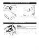
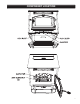
6041TP PEDESTAL TRIM ASSEMBLY Assemble trim pieces as shown with the screws provided in the parts bag. After trim assembly, attach to the pedestal base at the location shown using the screws provided. 2 6041HF ASSEMBLY 1 ASSEMBLY 1. Unpack unit and make sure all components are included; (4) Legs, and all hardware for installation. B B 2. Fold the corner padding from the carton and lay it on the floor behind the unit. This is used to hold the heater up off the floor to install the legs.
6041I ASSEMBLY DISCONNECT THE POWER CORD BEFORE SERVICING THIS HEATER (a) (a) (b) (e) (c) (h) (f) (g) (i) (j) (d) 4 B 3 2 REV A (k) A REV ISIO DES 1 INIT CRIPTION HIST IAL ORY N REL EAS 1.13 0.75 1.80 14.9 E 2 DAT 4/18 E /200 7 1.80 B.P. 3.00 15.2 6 B 0.38 60° 4 15.7 6 Flat SCA Pattern LE 1/ 3 (0.1 05) 3 TOLE RANC ES HOLES EXCE + .005" PT AS NOTE D -.001" DECIM .XX AL = 0.03 ANGU XXX = 0.010 LAR `2 ~ DESCR IPTION BLANK NUMB REFER 12 ER ENCE GA.
COMPONENT LOCATION 5
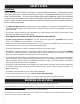
SAFETY STEPS IMPORTANT Proper installation of this heater is necessary for safe and efficient operation. Installing this product improperly may result in a house fire and personal injury. All applicable building codes for your location must be followed. In areas where building codes require additional steps to the installation of this product not included in this manual, the building codes will take precedent and must be followed.
BURNING SOLID FUELS continued... SHELLED CORN (Dry, preferably corn with 11- 12% moisture content) • Corn must contain less than 14% moisture content. Wet corn will rapidly deteriorate heater components, reduce efficiency and void all warranties. Purchase a moisture tester if in doubt. • Corn must be clean and free from debris. Never burn corn right from the field. Damage caused by dirty corn is not covered by the product warranty. Ask for clean filtered bagged corn only.
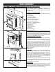
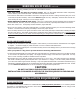
CLEARANCES TO COMBUSTIBLES 6041(TP)(HF) The heater must be installed with the following minimum clearances to side and back wall combustible materials. NOTE: These are minimum clearances to combustible walls established by the testing lab. PARALLEL - A BCD- Sidewall to Top Edge of Unit Sidewall to Flue Backwall to Flue Backwall to Unit 8 in./203mm 13 in./330mm 3 in./75mm 9 in./228mm CORNER - E - Adjacent Wall to Flue F - Adjacent Wall to Unit 3 in./75mm 4 in.
CLEARANCES TO COMBUSTIBLES 6041I 9
GUIDELINES FOR EXHAUST VENTING SYSTEMS DESIGN IMPORTANCE OF PROPER DRAFT Draft is the force which moves air from the appliance up through the chimney. The amount of draft in your chimney depends on the length of the chimney, local geography, nearby obstructions and other factors. Too much draft may cause excessive temperatures in the appliance. Inadequate draft may cause backpuffing into the room and ‘plugging’ of the chimney.
DO NOT CONNECT TO ANY AIR DISTRIBUTION DUCT OR SYSTEM VENT TERMINATION CLEARANCES: A) Min. 4-ft clearance below or beside any door or window that opens. B) Min. 1-ft clearance above any door or window that opens. C) Min. 3-ft clearance from any adjacent building. D) Min. 7-ft clearance from any grade when adjacent to public walkways. E) Min. 2-ft clearance above any grass, plants, or other combustible materials. F) Min. 3-ft clearance from a forced air intake of any appliance. G) Min.
DESIGN GUIDELINES FOR OUTSIDE COMBUSTION AIR CONNECTION 1. For installations with horizontal through-the-wall exhaust, it is strongly recommended that the heater combustion air be connected to the outside. If the home is newer or has been tightly insulated, it is required to install outside combustion air. 2. Connection to outside the house is REQUIRED for mobile home installations. We strongly urge use of the 69FAK Fresh Air Kit. 90 DEGREE BEND TERMINATION WIND HOOD TERMINATION Wind Hood 2” Min.
INSTALLATION CONFIGURATIONS The Multifuel Heater Model 6041TP/6041HF may be installed as follows: 1) A freestanding unit The Multifuel Heater Model 6041I insert may be installed as follows: 1) In a pre-fab firebox (Factory Built) 2) In an existing masonry fireplace 3) As a build-in MOBILE HOME INSTALLATION REQUIREMENTS IN ADDITION TO THE STANDARD INSTALLATION INSTRUCTION, THE FOLLOWING REQUIREMENTS ARE MANDATORY FOR INSTALLATION IN A MOBILE HOME: WARNING DO NOT INSTALL IN SLEEPING ROOM 1) Heater must be
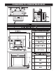
Note: Always check dimensions on unit before cutting hole in wall 2 1 3" PL Vent Termination Cap 3" PL Vent 90° Elbow A MINIMUM OF 3 VERTICAL FEET OF PIPE OUTSIDE THE HOME IS REQUIRED! 3" PL Vent (12" Long) EXHAUST OUTLET 3' DIA 10 1/16 B COMBUSTION AIR INTAKE 1 7/8" DIA 3" PL Tee w/ Cleanout 12 3" PL Vent (12" Long) Inner Wall Thimble 11 5/8 3" PL Vent (12" Long) Outer Wall Thimble *For illustrations purposes only 3 2 6041TP - PEDESTAL UNIT EXHAUST OULET 3" DIA.
THROUGH THE WALL, VERTICAL PIPE INSTALLATION WITH TERMINATION CAP A MINIMUM OF 3 VERTICAL FEET OF PIPE OUTSIDE THE HOME IS REQUIRED! The Hearth Pad is not required under the unit if the floor is noncombustible but is required 6 inches (152mm) beyond the front of the unit and 6 inches (152mm) beyond each side of the door if the floor is a combustible floor. (wood flooring, carpet, linoleum, etc.
DESIGN GUIDELINES FOR 6041I INSERT INSTALLATION A MINIMUM OF 3 VERTICAL FEET OF PIPE OUTSIDE THE HOME IS REQUIRED! INSTALLATION AS A BUILT-IN FIREPLACE A continuous sheet of non-combustible floor protection must be installed underneath the unit to prevent the possibility of embers falling through to the combustible floor. If the floor beneath the unit is of non-combustible material, the protector is not required. See the “Clearance to Combustibles” section of this manual for installation clearances.
DESIGN GUIDELINES FOR 6041I INSERT INSTALLATION INSTALLATION INTO A MASONRY FIREPLACE 4” VENT IS MANDATORY FOR INSERT INSTALLATIONS. When installing into a masonry fireplace, DO NOT remove any bricks or masonry, with the following exception: masonry or steel, including the damper plate, may be removed from the smoke shelf and adjacent damper frame, if necessary, to accommodate a chimney liner.
GLASS MAINTENANCE, REMOVAL AND REPLACEMENT Your Multi-Fuel Heater comes to you with the glass door installed in place, ready for use. The glass is surrounded on the edges with a gasket and seated in a glass channel. It is held in place with two (2) clips. This unit’s door uses a 1/2” diameter rope gasket. REMOVAL OF BROKEN OR DAMAGED CERAMIC GLASS Open the door and then lift it off of the hinges. If the door is tight, tap gently on the bottom of the door with your hand or rubber hammer.
UNDERSTANDING THE CONTROL BOARD CONTROL PANEL Turning the heater OFF/ON, as well as adjustments for the fuel feed rate and room fan speed are performed by pressing the appropriate button(s) on the control panel which is located on the lower left-hand side of your American Harvest heater. The insert model 6041I is located on the left facade. This unit has two fuel operation modes for different fuels, corn or pellet.
LIGHTING INSTRUCTIONS CAUTION: DO NOT USE CHEMICALS OR FLUIDS TO START THE FIRE. HOT WHILE IN OPERATION. KEEP CHILDREN, CLOTHING AND FURNITURE AWAY. CONTACT MAY CAUSE SKIN BURNS. Before lighting your heater for the first time, make sure that all items are out of the hopper, ash pan and firebox area. Close all doors and lids. Choose which fuel setting that you wish to operate in, Corn or Pellet.
• Fill the burnpot with wood pellets up to the level of the igniter port; See illustration. • Close all doors, lids, and cleanouts. • Press the “ON” button and select desired heat range. This will start the ignition sequence. Once the wood fuel is ignited and the heater senses heat, the auger and agitator will begin to rotate, feeding fuel to the burnpot. NOTE: If the starting fuel is not burning hot enough, you may see the fire begin to go out as new fuel is being added.
MAINTENANCE INSTRUCTIONS SOOT AND FLYASH - FORMATION AND NEED FOR REMOVAL The products of combustion will contain small particles of flyash. The flyash will collect in the exhaust venting system and restrict the flow of flue gases. Incomplete combustion, such as occurs during startup, shutdown, or incorrect operation of the room heater will lead to some soot formation which will collect in the exhaust venting system.
SPRING CLEANING When the heating season is over make sure that you clean out all of the fuel in the hopper, firebox area, ash pan and firepot area. Corn and any ash can accumulate moisture over the summer months causing the unit to rust and the fuel to mold. Corn left in the unit will attract mice and can cause internal wiring and insulation damage.
CONTROL BOARD FUNCTIONS START-UP SEQUENCE OF EVENTS Once the control panel is turned on, a timer begins that will start, stop and continue operation of the Multi-fuel Heater as a preset temperature is achieved. COMPONENT OPERATION START OPERATION END Draft Fan Starts Immediately Will continue until shutdown. Shutdown will occur when the operating temperature is below approx. 90 degrees.
ERROR CODES and DISPLAY INDICATORS Error Code Error Description Possible Causes Err1 The high limit temperature sensor • has tripped. • • • Err2 The low limit temperature sensor • Hopper Empty. has tripped. • Auger output failure or jam. • Poor flame or fuel quality caused fire to burn too slowly or go out. • Electrical Open in low temperature switch or wiring. • Fire was not well established before the PCB’s programmed time limit expired.
TROUBLE SHOOTING i Disconnect the power supply before performing any maintenance! NOTE: Turning the heater to “OFF” does not disconnect the power to all of the electrical components of the heater. i Never try to repair or replace any part of the heater unless instructions for doing so are given in this manual. All other work should be done by a trained technician. PROBLEM CAUSE: Too rich air/fuel mixture Orange, lazy flame, excessive fuel build-up in • Clean out the burnpot the burnpot.
WIRING DIAGRAM Insure the wires are connected to the bottom two prongs of the hopper switch as shown.
PARTS DIAGRAM - 6041TP 65 57 61 63 27 64 56 44 62 47 54 55 42 30 37 29 36 35 48 33 41 52 46 45 28 43 49 51 3 1 50 69 12 40 53 38 39 34 32 31 23 22 9 8 68 24 7 6 67 66 2 26 25 20 19 4 5 16 15 14 12 58 59 21 17 60 18 11 10 13 28
PARTS LIST - 6041TP Qty. Key Part No. Description Pedestal 1 36 891195 Drive Motor Bracket Pedestal Bottom 1 37 891169 Hose (2 per) 25451 Pedestal Back 1 38 891180 Auger Cover 69478 Ash Pan 1 39 88120 Gasket, 0.188 x 1.0 Flat FbrGlss.
PARTS DIAGRAM - 6041I 22 14 13 22 24 19 23 12 20 15 21 18 26 25 17 1 16 7 6 3 4 6 5 28 27 2 10 10 8 9 11 30
PARTS LIST - 6041I Key Part No. Description 1 891373 Pad, Door Hinge (Threaded) Qty.
PARTS DIAGRAM/LIST 7 6 5 8 1 10 11 3 4 3 2 4 9 Parts List 2 Key Part No. 1 25491 2 25492 3 4 5 88112 6 88087 Description Qty. Key Part No. Description Qty. Feed Door 1 7 891131 Glass Ceramic 1 Handle, Door 1 8 25464 Retainer, Top Glass 1 83506 Roll Pin, 3/8 x 1-1/4 1 9 25465 Retainer, Bottom Glass 1 891135 Handle, Spring (Parts Bag) 1 10 83202 Machine Screw 4 Gasket, 1/2” Sq.
NOTE 33
NOTE 34
NOTE 35
This manual will help you obtain efficient, dependable service from the furnace, and enable you to order repair parts correctly. Keep this manual in a safe place for future reference. When placing an order or for warranty claims, please provide the following information found on the Certification Plate located below the ash door. PART NUMBER PART DESCRIPTION MODEL NUMBER - 6041 / 6041TP / 6041HF / 6041I SERIAL NUMBER______________ 227 Industrial Park Road P.O.