Owner’s Operation and Instruction Manual MODEL 2500 SAFETY TESTED TO UL 1482 US ENVIRONMENTAL PROTECTION AGENCY PHASE II CERTIFIED WOODSTOVE WASHINGTON STATE APPROVED CAUTION! Read All Instructions Carefully Before Starting The Installation or Operating This Heater. SAFETY NOTICE: If this heater is not properly installed, a house fire may result. For your safety, follow the installation instructions. Contact local building or fire officials about restrictions and installation requirements in your area.
CONGRATULATIONS! You've purchased a heater from North America's oldest manufacturer of wood burning products. By heating with wood you're helping to CONSERVE ENERGY! Wood is our only Renewable Energy Resource. Please do your part to preserve our wood supply. Plant at least one tree each year. Future generations will thank you. The instructions pertainning to the installation of your wood stove comply with UL-1482 standards.
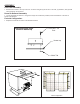
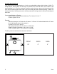
ASSEMBLY Flue Collar Assembly: 1. Mount the flue collar to the top of the unit as shown using the (3) 5/16-18 x 1-1/2 bolts, (3) washers, and (3) weld tabs provided in the parts box. Room Air Deflector Assembly: 1. Locate the Room Air Deflector. Using the three(3) 1/2 Tek Screws provided, mount the deflector to the unit as shown in the diagram. Firebrick Configuration: 1. Replace the Firebrick as shown in the illustration below.
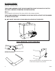
BLOWER ASSEMBLY ASSEMBLY INSTRUCTIONS THE BLOWER ASSEMBLY MUST BE DISCONNECTED FROM THE SOURCE OF ELECTRICAL SUPPLY BEFORE ATTEMPTING THE INSTALLATION. Step 1. Fix the assembly to the back of the stove with the four screws provided. THE BLOWER ASSEMBLY IS INTENDED FOR USE ONLY WITH A STOVE THAT IS MARKED TO INDICATE SUCH USE. DO NOT ROUTE THE SUPPLY CORD NEAR OR ACROSS HOT SURFACES! 2500 PEDESTAL TRIM ASSEMBLY Assemble trim pieces as shown with the screws provided in the parts bag.
INSTALLATION SAFETY NOTICE • IF THIS STOVE IS NOT PROPERLY INSTALLED, A HOUSE FIRE MAY RESULT. TO REDUCE THE RISK OF FIRE, FOLLOW THE INSTALLATION INSTRUCTIONS. FAILURE TO FOLLOW INSTRUCTIONS MAY RESULT IN PROPERTY DAMAGE, BODILY INJURY, OR EVEN DEATH. • CONSULT YOUR MUNICIPAL BUILDING DEPARTMENT OR FIRE OFFICIALS ABOUT RESTRICTIONS AND INSTALLATIONS REQUIREMENTS IN YOUR AREA. • USE SMOKE DETECTORS IN THE ROOM WHERE YOUR STOVE IS INSTALLED. • KEEP FURNITURE AND DRAPES WELL AWAY FROM THE STOVE.
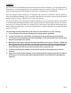
FLOOR PROTECTOR Your wood stove should be placed on a 1 inch, non-combustible surface with a k factor of 0.84. For multiple layers, add R-values of each layer to determine the overall R-value. The R value for the required board is 1.2. The floor protector should be under the stove, twenty-six inches beyond the front and six inches beyond each side of the fuel loading and ash removal opening.
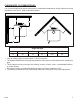
CLEARANCES TO COMBUSTIBLES It is of utmost importance that the clearances to combustible materials be strictly adhered to during installation of the stove. Refer to the tables below : Single wall pipe A B C D E F 12 20 16 30 10.5 20 • Floor to ceiling height must be at least 7’ (84”) in all cases. • The clearance between the flue pipe and a wall are valid only for verticle walls and for verticle flue pipe.
CHIMNEY Your wood stove may be hooked up with a factory built or masonry chimney. If you are using a factory built chimney, it must comply with UL 103 standard; therefore it must be a Type HT (2100°F). It is extremely important that it be installed according to the manufacturer's specifications. If you are using a masonry chimney, it is important that it be built in compliance with the specifications of the National Building Code.
CHIMNEY CONNECTOR (STOVE PIPE) Your chimney connector and chimney must have the same diameter as the stove outlet. If this is not the case, we recommend you contact your dealer in order to insure there will be no problem with the draft. The stove pipe must be made of aluminized or cold roll steel with a minimum thickness of 0.021" or 0.53 mm. It is strictly forbidden to use galvanized steel. Your smoke pipe should be assembled in such a way that the male section of the pipe faces down.
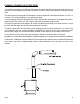
TYPICAL INSTALLATIONS FACTORY BUILT CHIMNEY : Wall Installation Vertical Installation 10 Ussc
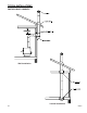
TYPICAL INSTALLATIONS continued...
TYPICAL INSTALLATIONS continued...
OUTSIDE COMBUSTION AIR Your 2500 stove is approved to be installed with an outside air intake which is necessary for a mobile home. This type of installation is also required in air tight houses and houses with negative pressure problems. You can purchase this option through your heater dealer. Make sure to specify the part number mentioned in this booklet. Installation instructions are supplied with the air intake kit. Outside combustion air may be required if : 1.
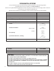
WOODSTOVE UTILIZATION Your heating unit was designed to burn wood only; no other materials should be burned. Waste and other flammable materials should not be burned in your stove. Any type of wood may be used in your stove, but specific varieties have better energy yields than others. Please consult the following table in order to make the best possible choice. TYPE WEIGHT PER CORD EFFICIENCY RANKING SPLITS MILLIONS BTU's/CORD (LBS. CU. FT., DRY) Hickory 63 4500 1.0 Well 31.
TESTING YOUR WOOD When the stove is thoroughly warmed, place one piece of split wood (about five inches in diameter) parallel to the door on the bed of red embers. Keep the air control full open by pulling on it and close the door. If ignition of the piece is accomplished within 90 seconds from the time if was placed in the stove, your wood is correctly dried. If ignition takes longer, your wood is damp.
WARNINGS • NEVER OVERFIRE YOUR STOVE. IF ANY PART OF THE STOVE STARTS TO GLOW RED, OVER FIRING IS HAPPENING. READJUST THE AIR INTAKE CONTROL AT A LOWER SETTING. • THE INSTALLATION OF A LOG CRADLE IS NOT RECOMMENDED IN YOUR WOOD STOVE. • NEVER PUT WOOD ABOVE THE FIREBRICK LINING OF THE FIREBOX. RELOADING Once you have obtained a good bed of embers, you should reload the unit. In order to do so, open the air controls to maximum a few seconds prior to opening the stove’s door.
ASH DISPOSAL Ashes should be removed from the stove every few days or when ashes get to 2 to 3 inches deep. Always empty the stove when it is cold, such as in the morning. Always dispose of ashes in a metal container with a tight fitting lid. Place this container on a non combustible floor or on the ground, well away from all combustible materials, pending final disposal.
REPAIR PARTS KEY 18 1 2 3 4 5 6 7 8 9 10 • 11 12 13 14 15 16 17 18 19 20 21 22 23 24 25 26 DESCRIPTION Feed Door Assy. Feed Door Latch Door Hinge Flue Collar 5/16-18 x 1-1/2 Bolt Washer Nut, 5/16-18 Air Deflector Ceramic Fiber Board Secondary Tubes - Front Secondary Tubes - Rear Tube Retainer Pedestal Front Pedestal Left Side Pedestal Right Side Pedestal Bottom - Left Pedestal Bottom - Right Pedestal Back Weld.
NOTES Ussc 19
HOW TO ORDER REPAIR PARTS THIS MANUAL WILL HELP YOU OBTAIN EFFICIENT, DEPENDABLE SERVICE FROM YOUR 2500 HEATER, AND ENABLE YOU TO ORDER REPAIR PARTS CORRECTLY. KEEP THIS MANUAL IN A SAFE PLACE FOR FUTURE REFERENCE. WHEN WRITING, ALWAYS GIVE THE FULL MODEL NUMBER WHICH IS ON THE NAMEPLATE ATTACHED TO THE HEATER. WHEN ORDERING REPAIR PARTS, ALWAYS GIVE THE FOLLOWING INFORMATION AS SHOWN IN THIS LIST: 1. THE PART NUMBER 2. THE PART DESCRIPTION 3. THE MODEL NUMBER: 2500 4.