
Brochure


Utica H
2
O Stainless Steel Storage Tanks
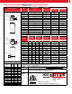
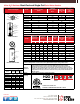
Dimensions/Weights Model
Storage Capacity
(Gals.)
Piping Connections NPT
Cold/Hot
Supply/Return
(Inches)
Heat Source
Pressure
(Inches)
Dimensions & Weights
Models
Height
(Inches)
Dia.
(Inches)
Shp. Wgt.
(Lbs.)
H2OST30UB
34.0 23.5 75
H2OST40UB
44.0 23.5 90
H2OST60UB
62.0 23.5 115
H2OST60LUB
46.0 23.5 110
H2OST80UB
56.0 28.0 140
H2OST115UB
74.0 28.0 175
H2OST80CUB
56.0 28.0 140
H2OST115CUB
74.0 28.0 175
H2OST30UB 30
1 1
H2OST40UB 40 1 1
H2OST60UB 60
1 1
H2OST60LUB 60 1 1
H2OST80UB 80 1 1
H2OST115UB 115 1 1
H2OST80CUB 80 1-1/2 1
H2OST115CUB 115 1-1/2 1
Note: Max. Working pressure 150 psi for all capacities.
General Information (See Installation, Operation and Maintenance Manual for complete instructions)
Specifications subject to change without notice.
Standard
Equipment
Factory installed brass drain and relief valves, welded stainless steel cold water dip
tube factory installed and pressure tested, Honeywell L4080B aquastat for field instal-
lation.
Options
(L) Low profile models for applications with low clearances.
(C) Commercial models available for applications with larger connections.
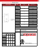
Certification/
Decoding
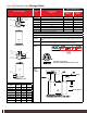
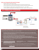
Schematic
Diagram
(Typical
Installation)
H2O
ST
=
Storage Tank L
=
Lowboy
C
=
Commercial
UB
=
Utica BoilerCapacity:
30
=
30 Gals.
40
=
40 Gals.
60
=
60 Gals.
80
=
80 Gals.
115
=
115 Gals.
L UBST
TOP CONNECTIONS
ALL 1" NPT
COLD
WATER INLET
SUPPLY TO
HEAT SOURCE
HOT OUTLET
T+P VALVE
RETURN FROM
HEAT SOURCE
8.0
8.0
STANDARD UNITS
AQUASTAT
WELL
DRAIN
T+P VALVE
1" NPT SUPPLY
TO HEAT SOURCE
1" NPT RETURN
FROM HEAT SOURCE
1 1/2" NPT
COLD INLET
AQUASTAT
WELL
DRAIN
COMMERCIAL UNITS
8.0
8.0
9.5
3/4" NPT
RECIRC. PORT
1 1/2" NPT
HOT OUTLET
Conforms to UL STD 174
Certied to CAN/CSA STD C22.2 No. 110-94