
Brochure
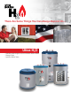

Utica H
2
O Stainless Steel Buffer Tanks
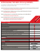
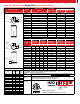
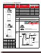
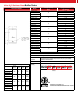
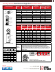
Dimensions/Weights Model
Storage Capacity
(Gals.)
Piping Connections
NPT (Inches)
Dimensions & Weights
Model
Height
A
(Inches)
B
(Inches)
C
(Inches)
Shp. Wgt.
(Lbs.)
H2O40BT114UB
42.0 31 11
87
(97 WC)
H2O40BT112UB
H2O40BT2UB
H2O60BT114UB
44.0 31.5 11.5
115
(125 WC)
H2O60BT112UB
H2O60BT2UB
H2O80BT114UB
54.0 40.5 11.5
125
(135 WC)
H2O80BT112UB
H2O80BT2UB
H2O115BT114UB
72.0 61.5 11.5
160
(170 WC)
H2O115BT112UB
H2O115BT2UB
H2OBT40114UB
40
1-1/4
H2OBT40112UB 1-1/2
H2OBT402UB
2
H2OBT60114UB
60
1-1/4
H2OBT60112UB 1-1/2
H2OBT602UB 2
H2OBT80112UB
80
1-1/4
H2OBT80114UB 1-1/2
H2OBT802UB 2
H2OBT115114UB
115
1-1/4
H2OBT115112UB 1-1/2
H2OBT1152UB 2
H2OBT40114WCUB
40
1-1/4
H2OBT40112WCUB 1-1/2
H2OBT402WCUB
2
H2OBT60114WCUB
60
1-1/4
H2OBT60112WCUB 1-1/2
H2OBT602WCUB 2
H2OBT80114WCUB
80
1-1/4
H2OBT80112WCUB 1-1/2
H2OBT802WCUB 2
H2OBT115114WCUB
115
1-1/4
H2OBT115112WCUB 1-1/2
H2OBT1152WCUB 2
Note: Max. Working pressure 60 psi for all capacities.
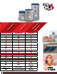
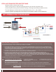
General Information (See Installation, Operation and Maintenance Manual for complete instructions)
Specifications subject to change without notice.
Standard
Equipment
Factory installed brass drain and relief valves, welded stainless steel cold
water dip tube factory installed and pressure tested, Honeywell L4080B
aquastat for field installation.
Options (WC) With Coil
Certification/
Decoding
Conforms to UL STD 174
Certied to CAN/CSA STD C22.2 No. 110-94
H2O
BT
=
Buffer Tank 114
=
1-1/4” NPT
112
=
1-1/2” NPT
2
=
2” NPT
UB
=
Utica BoilerCapacity:
40
=
40 Gals.
60
=
60 Gals.
80
=
80 Gals.
115
=
115 Gals.
114
WC
=
With Coil
WC UBBT
40