
Brochure
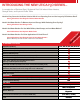

Buffer Tank Sizing - Calculating Capacity
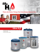
Utica H
2
O buffer tanks are a simple, cost effective way to improve overall system efciency by reducing unnecessary equipment short cycling.
The recommended capacity or volume of a buffer tank is based on four variables.
1) The duration of the heating or cooling source “on time” (minutes). The desired length of “on time” for each run cycle depends on the
type of equipment used. Heat pump and chiller manufacturers typically recommend a minimum of 5 to 10 minutes on time, and boiler
manufacturers may recommend a minimum of 10 minutes “on time”. Check with your equipment manufacturer. Generally, the longer the
“on time”, the higher the overall operating efciency.
2) The minimum rate of heat input (BTU/HR). This is based on the heat pump or chiller output, or the boiler output at the minimum ring rate if
the boiler has a variable input system that ramps input down as the demand decreases.
3) The minimum system load (BTU/HR). This is the demand placed on the system with the smallest zone calling for heat.
4) The allowable tank temperature rise (deg. F). This varies depending on the type of heating or cooling system used, and on the
design of the distribution system. Chillers may require a tight, (6 deg. F), differential to assure good dehumidication and prevent freezing,
heat pumps may require a (10 deg. F) differential to maintain a high COP, and boilers with hydronic heating distribution systems may require
a differential anywhere between 10 to 40 deg. F depending on the application.
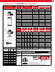
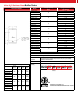
The following formula determines the tank volume:
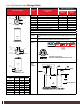
UTICA H
2
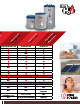
O STAINLESS STEEL BUFFER TANKS
•
Reduces chiller or boiler short cycling
(Short cycling results in reduced operating efciency and shorter equipment life)
•
Used in systems having several low BTU cooling or heating loads calling at different times
•
Full size tappings on buffer tank for peak performance (1-1/4”, 1-1/2”, and 2”)
• Used in systems operating below the design load condition, which is most of the time.
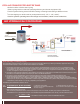
H
2
O HYDRAULICALLY DECOUPLED
To/From
Boiler/Chiller/Heat-Pump
Buffer Tanks
To/From
System
V = Buffer tank volume (gallons) T = desired heat source “on cycle” (min.)
Q heat source = heat source output (BTU/HR) Q min. heat load = heat output to minimum load
Tank temp rise (deg. F)
V
=
T X (
Q heat input - Q min. heat load
)
Tank temp. rise
X 500
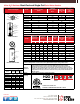
Water to Water Heat Pump Example:
Town and Country Mechanical wants a minimum heat pump on time of 10 minutes. The heat pump output is 46,500 BTU/HR.
The smallest zone is a 7,000 BTU/HR bathroom. The allowable temperature differential is 90 to 100 deg. F for the radiant heat zones.
=
79.0 Gallons minimum volume. Choose the H2O80BT buffer tank.
V
=
10
x (
46,500 - 7,000
)
(
100-90
) x 500