
Owner's manual


Page 4/8
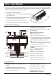
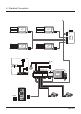
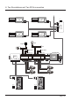
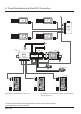
5. Terminal Connections
1 2 3 4 5 6
ON
1 2 3 4
ON
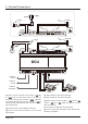
Connect to
Bus line
Connect to
Bus line
COM
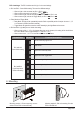
Adapter
Exit Button
Light Button
Lamp
Camera 1
+
+ +
-
- -
+
-
Camera 2
NC/NO
COMNC/NO
Connect to
Door Station
AC
DCU
+
-
Switch
Switch
[2]
[7]
[6]
[5]
[1]
[3]
[3]
[4]
[5]
[8]
[4]
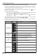
[1] When connect a electroic lock, set Bit-1 = ON, Bit-
2 = OFF of DIP-4 to select lock control. If the lock is a
Power-on-to-Unlock type, set Bit-3 = OFF of the DIP-
6 to select Normally Open mode), set Bit-3 = ON to
select Normally Closed mode when connect a Power-
Off-to-Unlock type.
[2] Please use the correct adapter for the lock.
[3] Please connect with the Button, do not connect
with a switch.
[4] DIP-6 switches, must be set correctly.
[5] DIP-4 switches, must be set correctly.
[6] When connect a light, set Bit-1 = OFF, Bit-2 = ON
or Bit-1 = ON, Bit-2 = ON of DIP-4 to select one of the
light control mode.
[7] Connect to AC electricity from 100~250V.
[8] CCTV camera, the rated power of the camera must
less than 12V 500mA.