For the installer Installation and maintenance instructions ecoTEC exclusive Gas wall boilers with condensing appliance technology GB, IE ecoTEC exclusive 832 ecoTEC exclusive 838
Contents 1 1.1 1.2 1.3 Notes on the documentation........................... Storage of the documents ...................................... Safety instructions and symbols ........................... Validity of the manual ............................................. 2 2.1 2.2 2.3 2.4 2.5 2.6 Description of the appliance ........................... 4 Design .......................................................................... 4 Type overview .......................................................
Contents Notes on the documentation 1 1 Notes on the documentation 9.1.3 9.1.4 9.2 9.3 Error codes ................................................................. Error memory ............................................................ Test programs............................................................ Resetting parameter to factory settings ............ 45 45 46 46 10 10.1 10.2 10.3 10.4 10.5 Replacing components ..................................... Safety instructions .....................
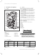
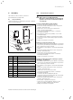
2 Description of the appliance 2 Description of the appliance 2.1 Design 14 1 13 2 3 4 12 5 11 6 7 10 8 2.
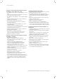
Description of the appliance 2 Safety instructions and regulations 3 2.4 3 Gas council numbers Appliance Gas council numbers ecoTEC exclusive 832 ecoTEC exclusive 838 47 044 37 47 044 38 Table 2.2 Gas council numbers 2.5 Intended use The Vaillant ecoTEC exclusive is a state-of-the-art appliance which has been constructed in accordance with recognised safety regulations.
3 Safety instructions and regulations 3.2 Related documents The installation of the appliance and any associated hot water system must be in accordance with (but not limited to) the following; COSHH regulations, Gas Safety (Installation and Use) Regulations 1998, Health and Safety Document No. 635 (The Electricity at Work Regulations 1989), BS7671 (IEE Wiring Regulations) and the Water Supply (Water Fitting) Regulations 1999, or The Water Bylaws 2000 (Scotland).
Assembly 4 4 Assembly 4.1.1 The Vaillant ecoTEC exclusive is delivered pre-assembled in a package unit. a Important: With regards to the Manual Handling 4.1 Scope of delivery Check the delivery for completeness and lack of damage (see Fig. 4.1 and Table 4.1). 2 3 1 4 5 10 6 Transporting the appliance 7 8 9 Fig. 4.
4 Assembly Carriage of carton from point of delivery to point of installation – first or higher floor, cellar. • Recommend 2-person lift or 1 person with use of sack truck. • If 1 person is performing lift, straddle the load, tilt and place carton into position on truck. • Recommend secure appliance onto truck with suitable straps. • Ensure safe lifting techniques are used – keep back straight – bend using legs. • Keep load as close to body as possible.
Assembly 4 Positioning of Appliance for Final Installation – above worktop, foreseeable obstructions etc. • If appliance weight is over 25 kg always use 2 persons to move where practical. • Fit bracket securely onto wall before lifting appliance into position. • Obtain firm grip on front and sides of appliance, lift upwards, onto worktop if practicable. • Ensure stable balance achieved and lift upwards to position in place on bracket.
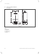
4 Assembly 4.2 Dimensioned drawing and dimensions for connection 190 480 7 4 3 Ø 20 Ø 20 70 100 100 7 25 Ø 20 5 20 6 R 1/2 800 2 180 450 Fig. 4.
Assembly 4 Particularly in hairdessing salons, lacquering and finishing workshops, cleaning facilities, etc., the appliance must be operated independently of the ambient air. Otherwise, a separate installation room is required to guarantee that the combustion air supply is free from the above substances. Required minimum gaps/assembly clearances e Danger! Danger of death by electric shock! If a room In the event of installation in unusual locations, special provisions may have to be made.
4 Assembly 5 Installation 4.5 Mounting the appliance 240 75 75 2 50 50 5 d Danger! The Vaillant ecoTEC exclusive may only be installed by a suitably qualified heating engineer approved at the time by the Health and Safety Executive who also assumes the responsibility for installing the appliance properly and fully commissioning the appliance prior to first use, along with demonstrating its correct use to the end user. 85 23 1 5.
Installation 5 5.3 Hot water and cold water connections 5 2 4 1 2 3 Fig. 5.2 Hot water and cold water connection a Caution! Mount the hot water and cold water lines so they are tension-free, this prevents leaks! Fig. 5.1 Gas connection The Vaillant ecoTEC exclusive is supplied for use with natural gas G20 and can only be converted to the use of propane gas G31 by the Vaillant service engineer or a suitably qualified installer approved at the time by the Health and Safety Executive.
5 Installation 5.4 Heating connection Fig. 5.3 Heating connection a Caution! Mount the heating lines so they are tension-free, this prevents leaks! Before connecting the heating circuit to the boiler, all pipework and radiators must be thoroughly flushed to remove any installation debris. • Connect the central heating flow and return service valves to the appliance. • Connect the 22 mm copper pipe tails to the service valves as shown in the illustration and tighten the nuts.
Installation 5 5.6 Flue pipe d Danger! Vaillant appliances are only system-certified if genuine Vaillant flue pipes are used. Only use genuine Vaillant flue pipes. Malfunctions can occur if you use other accessories. These may result in damage and injury. You will find a list of genuine flue pipes in the Vaillant installation manual for flue pipes. The CE mark is valid only if the appliance is operated with Vaillant flue pipes. 1103 70 100 mm standard flue pipe 70 5.6.1 5.6.
5 Installation BS 5440–1: We recommend that the terminal of a fan-assisted flue pipe system be positioned as follows: a) At least 2 m from an opening in the building directly opposite, and b) so that the combustion products do not flow out at right angles to a boundry. A G H, I F B F G BCD J A A E F M F L K LK A G Fig. 5.9 Terminal Locations h Note! Vertical flue pipes must not terminate within 600 mm of an opening window, an extraction opening or any other ventilation opening.
Installation 5 5.9 The condensate drain pipe should have a minimum diameter of 22 mm, without length restriction, and also be fitted with a siphon (3) having a connection head of 75 mm (fitted within the boiler already). The connection should be made after the drain siphon if possible. If the installation is only possible in front of the siphon, there must be a ventilation valve between the two siphons. This is normally provided in a drain.
5 Installation 5.10.2 Connection of controllers, accessories and external installation components The following controllers, accessories and installation components can be connected to the ecoTEC exclusive (see Table 5.2). The installation should be carried out in accordance with the individual instruction manual. The required connections to the electronic system of the boiler (e.g. for external controllers, external sensors etc.
Installation 5 5.10.4 Details for the connection of an external timer to the connection rail 20 VDC 7 8 (DO NOT USE 7, 8, 9 IN UK!) 9 L N 5 3 4 N L SWITCH CONTACTS 3 A FUSE ROOM THERMOSTAT MAINS SUPPLY 230 V 50 Hz L N CLOCK N Fig. 5.
5 Installation 5.10.
Installation 5 Flow temperature sensor (NTC) Return temperature sensor (NTC) Ignition electrode X 20/5 red X 20/7 black X 20/8 blue X 20/7 black Plug connection Gas valve Fan X 20/16 blue (Earth) X 20/4 grey (PWM) X 20/3 black (Hall signal) X 20/18 red (24 VDC) X 20/17 red (24 VDC) X 20/9 blue (Earth) X 2/16 black A X 2/7 pink B X 2/15 brown C Water pressure sensor X 2/8 blue D Preference changeover valve X 2/9 black Water through flow sensor X 2/11 red X 2/12 green Pump X 2/4 orange X 2/3 r
6 Start-up 6 Start-up 6.1 Filling the installation Mixing additives with the heating water can result in material damage. However, up to now, no incompatibility with Vaillant appliances has been detected with proper use of the following products. • When using additives, follow the additive manufacturer‘s instructions without exception. Vaillant accepts no liability for the compatibility of any additive or its effectiveness in the entire heating system.
Start-up 6 a Caution! h Note! Risk of material damage if the heating water is The ecoTEC units are supplied with a pressure treated with unsuitable frost or corrosion protection agents! Frost and corrosion protection agents may cause changes in the seals, noises during heating and possibly subsequent damage. Do not use any unsuitable frost or corrosion protection agents. 6.1.1 Filling and bleeding from the heating side gauge and a digital pressure display (2).
6 Start-up • Repeat this at all radiators until the complete system is full, all air locks have been cleared and the boiler pressure gauge reads 1.5 bar. Release any air from the pump by slackening the centre screw. Turn off the filling valve (2) and fully close filling valve (1). • The boiler is equipped with an automatic air release valve.
Start-up 6 The combustion of this boiler has been checked, adjusted and preset at the factory for operation on the type of gas defined on the identification plate. No measurement of the combustion is necessary to set up the boiler. • Do not adjust the multifunctional automatic gas valve.
6 Start-up 6.2.3 Checking the gas inlet working pressure • Ensure that the gas inlet working pressure can be obtained with all other gas appliances in the property working. • Remove the front casing from the boiler. • Close the gas isolation valve of the boiler. • In addition, ensure that maximum heat can be dissipated into the heating system by turning up the room thermostat. • Alternatively, fully open the hot water taps to ensure full flow rate through the boiler.
Start-up 6 If the gas inlet working pressure is within the permissible range, proceed as follows: • Take the boiler out of operation by - Pressing the + and i buttons simultaneously and turn down both thermostat control knobs. - Allow the boiler to cool down by turning off water taps and allow pump overrun to operate for a minimum of two minutes. • Close the gas isolation valve of the boiler. • Remove the pressure gauge and re-tighten the sealing screw (1). • Open the gas isolation valve of the boiler.
6 Start-up 6.3.2 Hot water function • Switch on the appliance. • Turn on a hot water tap fully. • Press "i" to activate the status indicator. When the hot water function is working correctly the display shows "S.14". Fig. 6.9 Display during hot water preparation 6.3.3 • • • • • • • • • • Subsequent flushing through of the heating system ("hot") Allow the appliance to run until both the appliance and the heating system have reached their operating temperature. Check the heating system for leaks.
Adapting the appliance to the heating system 7 7 Adapting the appliance to the heating system The ecoTEC exclusive units are fitted with a digital information and analysis system. + 7.1 Selection and setting the parameters In the diagnostic mode, you can change the various parameters required to match the boiler to the heating system. Table 7.1 shows only those diagnostic points where modifications are possible.
7 Adapting the appliance to the heating system 7.2 Overview of the settable installation parameters The following parameters can be set to match the appliance to the heating system and to suit the customers requirements: Adjustable parameters Default setting 22 kW 27 kW Display Meaning d.0 Heating partial load ecoTEC exclusive 832 27 kW ecoTEC exclusive 838 30 kW d.1 Pump overrun time for heating operation (starts after completion of heat demand) 2 - 60 min 5 min d.2 Max.
Adapting the appliance to the heating system 7 7.2.
7 Adapting the appliance to the heating system 7.2.7 Setting the pump output The ecoTEC exclusive is fitted with a speed controlled pump which sets itself to the hydraulic conditions and the heat demand of the heating system. Under certain conditions the output of the pump can be set, in five steps to 53, 60, 70, 85 or 100% of the maximum pump output using the diagnosis system. This switches the speed control off. Lift [mbar] a 7.3 Adjusting the bypass valve The appliances have a bypass valve.
Inspection and maintenance 8 8 8.1 Inspection and maintenance Inspection and maintenance intervals Danger! Risk of injury and risk of damage to property due to neglected inspection and maintenance! Neglected inspection and maintenance works or not observing the stated inspection and maintenance intervals can interfere with the operational safety of the boiler and can result in damage to property and to persons.
8 Inspection and maintenance - The gas flow rates as described in Section 6.2.2. Correctness of electrical, water and gas connections. Correctness of the water pressure. The condition of the whole system, in particular the condition of radiator valves, evidence of leakage from the heating system and dripping taps. • Correct any faults before proceeding. 8.1.2 • Check the boiler for gas and water leaks. • If necessary, refill and re-bleed the heating installation.
Inspection and maintenance 8 • Measure the CO2 concentration at the flue gas analysis point (1). Compare the measured value with the corresponding value in Table 8.1. • If all these points are as required, proceed as described in Section 8.1.5. • If one of the flue gas values is greater than the acceptable values in Table 8.1, then proceed as described in the following Section 8.1.4. 8.1.
8 Inspection and maintenance 8.1.5 Inspection and maintenance work steps Column 2 Maintenance Column 1 must be carried Inspection must out at regular be carried out intervals – but each year no longer than 5 years No. Activity 1 Check the air flue gas installation for leaks and for proper fixation and ensure it is not blocked or damaged and is fitted correctly, complying with the relevant installation instructions.
Inspection and maintenance 8 8.2 Filling/draining the heating installation 1 8.2.1 Filling the unit and heating installation The filling of the appliance and the heating system is described in Section 6.1. 2 8.2.2 Draining the unit • Close the maintenance cocks (if fitted) on the appliance. • Open the drain valves on the maintenance cocks. 3 4 8.2.3 Draining the entire installation • Attach a hose to the filling/draining cock on the system.
8 Inspection and maintenance 8.3.2 Clean the heat exchanger 8.3.4 Installing the burner assembly a Caution! Protect the electronics box turned down 1 against sprayed water. 2 1 Fig. 8.5 Replacing silicone gaskets 2 • Insert the new graphite seals (1) in the burner flange. 3 a Danger! The two seals (1 - Fig. 8.5) on the burner assembly 4 (must be replaced each time the module is removed (for example during maintenance). The burner flange insulation (2 - Fig. 8.
Inspection and maintenance 8 • Only ecoTEC exclusive 832: Insert the cables on the fan motor and the cable on the gas fitting. Only ecoTEC exclusive 838: Close the mains coupling to the fan. • Connect the gas supply (6) with a new gasket to the gas fitting. Use the spanner flat at the flexible gas line to hold the gas line. a Caution! Open the gas supply and check the appliance for gas leaks using a leak testing spray. Pay particular attention to the gas fitting (6).
8 Inspection and maintenance 8.6 8.7 Checking the connection pressure (gas inlet working pressure) To check the connection pressure proceed as described in Section 6.2.3. Checking the expansion vessel 8.8 1 Checking CO2 content and adjusting if necessary To check the air figure proceed as described in Section 8.1.3. 8.
Troubleshooting 9 9 Troubleshooting h Note! If you wish to contact the Vaillant Service Team, please refer to the error code displayed (F.xx) and the appliance status (S.xx) if possible. Display Meaning Heating mode 9.1 Diagnostics 9.1.1 Status codes The status codes that you can see on the display provides information about the current operating condition of the appliance. S.0 S.1 S.2 S.3 S.4 S.5 S.6 S.7 S.
9 Troubleshooting 9.1.2 Diagnosis codes In the diagnosis mode, you can change certain parameters or display more information. The diagnosis information is divided into two diagnosis levels. The 2nd diagnosis level can be reached only after entering a password. a Caution! The access to the 2nd diagnosis level may only be used by a qualified heating engineer. 1st diagnosis level • Press the "i" and "+" buttons simultaneously. The display shows "d.0".
Troubleshooting 9 Display Meaning Display value/adjustable value d.0 Heating partial load adjustable heating partial load in kW d.1 Water pump return time for heating mode 2 - 60 minutes (factory setting: 5) d.2 Max. blocking time heating at 20°C feed temperature 2 - 60 minutes (factory setting: 20) d.3 Measured value for the hot water outlet temperature in °C d.4 Measured value for the hot start sensor in °C d.
9 Troubleshooting Display 1) Meaning Display value/adjustable value d.14 Pump speed target value target value internal pump in % - possible settings: 0=Auto, 1=53, 2=60, 3=70, 4=85, 5=100 % (Factory setting: Auto) d.17 Heating flow/return regulation changeover 0 = flow, 1 = return (factory setting: 0) d.
Troubleshooting 9 9.1.3 Error codes The error codes displace all other displays when errors occur. If many errors occur simultaneously, the relevant error codes are displayed alternately for approx. 2 seconds each. You can exit the error memory display as follows: • Press the "i" button or • Do not press any button for about 4 minutes. The current heating flow temperature appears in the display again. 9.1.4 Error memory The last ten errors are saved in the appliance error memory.
9 Troubleshooting Code Meaning Cause F.71 Constant value feed NTC Feed NTC faulty F.
Replacing components 10 10 Replacing components The tasks listed below in this section may be carried out only by a heating engineer approved at the time by the Health and Safety Executive. • Only use genuine spare parts for repairs. • Make sure the parts are correctly fitted and that their original position and alignment are retained. 10.1 • Release the 4 screws (1) on burner, and remove the burner. • Mount the new burner with a new gasket.
10 Replacing components • Release both fixing screws (5) on the gas fitting and remove the fan from the gas fitting. • Replace the defective component. • Remove the clamps (4) on the trap (3), release the fittings on the trap and remove the trap from the primary heat exchanger. • Remove the adaptor nuts of the trap from the primary heat exchanger. • Release the return connection (6) and the feed connection (5) on the primary heat exchanger.
Vaillant service 11 Recycling and disposal 12 11 Vaillant service To ensure regular servicing, it is strongly recommended that arrangements are made for a Maintenance Agreement. Please contact Vaillant Service Solutions (0870 6060 777) for further details. 12 Recycling and disposal Both your Valliant ecoTEC exclusive and its packaging consist mainly of recyclable raw materials. The Vaillant ecoTEC exclusive and all accessories and the packaging must not be disposed of in the household waste.
13 Technical data 13 Technical data ecoTEC exclusive 832 838 Unit Nominal heat output range P at 40/30 °C 11,0 - 29,3 12,1 - 32,4 kW Nominal heat output range P at 50/30 °C 10,8 - 28,7 11,9 - 31,8 kW Nominal heat output range P at 60/40 °C 10,5 - 27,9 11,5 - 30,9 kW Nominal heat output range P at 80/60 °C 10,2 - 27,0 11,2 - 30,0 kW Hot water output 31,4 37,2 kW Maximum load in hot water function 32 38 kW Maximum thermal load on heating-side 27,6 30,6 kW Minimum thermal loa
Appendix Appendix EC declaration of conformity Installation and maintenance instructions ecoTEC exclusive 0020017768_05 51
Installation, Commissioning and Service Record 52 Installation and maintenance instructions ecoTEC exclusive 0020017768_05
Please affix the label from the rear cover of the control box over this area.
SERVICE INTERVAL RECORD 0020008345-06 It is recommended that your heating system is serviced regularly and that you complete the appropriate Service Interval Record Below . Service Provider. Before completing the appropriate Service Interval Record below, please ensure you have carried out the service as described in the boiler manufacturer’s instructions. Always use the manufacturer ‘s specified spare part when replacing all controls.
0020017768_05 GBIE 062010 — Subject to alterations