USER'S GUIDE Vaisala HMDW110 Series Humidity and Temperature Transmitters M211726EN-A
PUBLISHED BY Vaisala Oyj Street address: Mailing address: Phone: Fax: Vanha Nurmijärventie 21, FI-01670 Vantaa, Finland P.O. Box 26, FI-00421 Helsinki, Finland +358 9 8949 1 +358 9 8949 2227 Visit our Internet pages at www.vaisala.com.
Table of Contents 1 General Information About This Document Documentation Conventions Safety ESD Protection Recycling Trademarks Software License Warranty 3 3 3 4 4 4 4 5 5 2 Product Overview 6 HMDW110 Series Overview Output Parameters Explained HMD110/112 Parts HMW110/112 Parts HMS110/112 Parts Component Board Analog Output Overrange Behavior 6 7 8 9 10 11 12 3 Installation Selecting Location HMD110/112 Installation HMW110/112 Installation HMS110/112 Installation Wiring HMDW110 Wiring Both Current Lo
5 Maintenance Cleaning Calibration and Adjustment Adjustment Types Adjustment Points Calibration and Adjustment Using a Hand-Held Meter and a Reference Probe One-Point Humidity Calibration and Adjustment Using a Hand-Held Meter and HMK15 Humidity Calibrator Two-Point Humidity Calibration and Adjustment using a computer and a HMK15 Humidity Calibrator Two-Point Temperature Calibration and Adjustment using a Computer Replacing the HUMICAP® Sensor on HMD110/112 and HMW110/112 Replacing the HUMICAP® Sensor on H
1 General Information 1 GENERAL INFORMATION About This Document This document provides information for installing, operating, and maintaining HMDW110 series transmitters. Table 1 Version Information Document Code Description M211726EN-A This document. July 2014. First version.
1 General Information Safety The HMDW110 series transmitter delivered to you has been tested for safety and approved as shipped from the factory. Note the following precautions: Do not modify the unit. Improper modification can damage the product or lead to malfunction. ESD Protection Electrostatic Discharge (ESD) can cause immediate or latent damage to electronic circuits. Vaisala products are adequately protected against ESD for their intended use.
1 General Information Software License This product contains software developed by Vaisala. Use of the software is governed by license terms and conditions included in the applicable supply contract or, in the absence of separate license terms and conditions, by the General License Conditions of Vaisala Group. Warranty Visit our Internet pages for more information and our standard warranty terms and conditions: www.vaisala.com/warranty.
2 Product Overview 2 PRODUCT OVERVIEW HMDW110 Series Overview HMDW110 series transmitters are accurate humidity and temperature transmitters for measurements in HVAC and cleanroom applications. The series consists of the following models: n HMD110/112 models for installation in ventilation ducts n HMW110/112 models for wall installation n HMS110/112 models for outdoor use All models are loop-powered, with 2-wire current outputs for humidity and temperature.
2 Product Overview Output Parameters Explained HMDW110 series transmitters offer several output parameters. Relative humidity (RH) and temperature (T) are the measured parameters, the others are calculated based on RH and T. Table 3 HMDW110 Series Output Parameters Parameter Symbol Units Temperature T °C °F Description Temperature in Celsius or Fahrenheit scale.
2 Product Overview HMD110/112 Parts Figure 1 HMD110/112 Parts 1= 2= 3= 4= 5= 6= 7= 8= 8 PTFE membrane filter. Sensors for humidity and temperature. Fastening flange. Tightening screw for fastening flange. Type label. Transmitter cover. Component board. See Component Board on page 11. Cable glands for 4 ... 8 mm diameter cable.
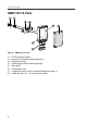
2 Product Overview HMW110/112 Parts Figure 2 HMW110/112 Parts 1= 2= 3= 4= 5= 6= 7= 8= Screw holes for mounting (2 pcs). Cable gland. Sensors for humidity and temperature. PTFE filter. Type label. Component board. See Component Board on page 11. Probe. Transmitter cover with captive screws.
2 Product Overview HMS110/112 Parts Figure 3 HMS110/112 Parts 1 = Radiation shield. Do not remove for installation, only when replacing the sensor or filter. 2 = Long screws that keep the radiation shield in place (2 pcs), 3 mm hex socket. 3 = Sensors for humidity and temperature under PTFE membrane filter. 4 = Component board. See Component Board on the facing page. 5 = Transmitter body. 6 = Screws for pole mounting (2 pcs, medium size Pozidriv). 7 = Clamp for pole mounting.
2 Product Overview Component Board All HMDW110 transmitter models use the same component board and have two 4 ... 20 mA outputs (loop powered). There is also a service port for configuration and calibration use. Figure 4 HMDW110 Series Component Board 1 = Terminal block for 4 ... 20 mA current loop outputs. 2 = Service port connector (4-pin M8). 3 = Terminal block for RS-485 output to RDP100 display panel (optional).
2 Product Overview Analog Output Overrange Behavior Analog outputs of the HMDW100 series transmitters have a defined behavior when the values measured by the transmitter are outside the scaled analog output range: n n n Output is clipped at the end of the scaled output range. You can allow the output exceed the scaled range by 10% with the aover serial command. Output is set to error state (default 3.6 mA) if an error is active (for example, due to sensor damage).
3 Installation 3 INSTALLATION Selecting Location When mounting duct model transmitters: n Avoid installing in a location where condensation may fall on the sensor inside the duct. n Position the sensor in the center of the duct. Select a site where the transmitter can be installed horizontally, onto the side of the duct. Do not point the probe downward, as this will make condensation run down to the sensor.
3 Installation HMD110/112 Installation n n n n n Medium size crosshead screwdriver (Pozidriv) for screws on cover and flange. Small slotted screwdriver for screw terminals. Drill with 2.5 mm and 13 mm bits for making the installation holes. Tools for cutting and stripping wires. 19 mm open-end wrench for tightening the cable gland. Figure 5 HMD110/112 Installation 1. Remove the yellow transport protection cap and separate the fastening flange from the transmitter. 2.
3 Installation 4. Push the probe of the transmitter through the flange and into the duct.The probe should reach far enough so that the sensor is located in the middle of the duct. Figure 6 HMD110/112 Centering Inside Duct 5. Secure the transmitter to the flange by tightening the screw on the flange that holds the probe in place. 6. Open the transmitter cover, and route the cables through the cable glands.
3 Installation HMW110/112 Installation n n n n n n Medium size crosshead screwdriver (Pozidriv) for cover screws. Small slotted screwdriver for screw terminals. Two installation screws: Ø ≤ 3.5 mm, head Ø ≤ 8 mm. Depending on the wall material and screw type, you may need a drill and a suitable drill bit to make installation holes for screws. Tools for cutting and stripping wires. 19 mm open-end wrench for tightening the cable gland. Figure 7 HMW110/112 Installation 1.
3 Installation 2. Open the transmitter cover, and route the cable through the cable gland. Connect the wires to the screw terminals according to the wiring instructions: o Wiring HMDW110 on page 19 o Wiring HMDW110 with RDP100 on page 21 For the arrangement of the screw terminals, see section Component Board on page 11. 3. Tighten the cable gland and close the transmitter cover. 4. Remove the yellow transport protection cap from the probe.
3 Installation 3. Adjust the length of cable between the cable gland and the terminal blocks. Make the cable short enough to close the cover without leaving a cable loop in the transmitter. 4. Disconnect the wired screw terminal blocks by pulling them off from the component board. 100 mm Ø 5.5 mm 18 5. Mount the transmitter according to the type of the installation site: o Pole installation a. Use the supplied clamp and screws to mount the transmitter on a pole. b.
3 Installation 6. Plug in the screw terminal blocks, close the cover, and tighten the screws. 7. Secure the cable to the pole using a zip tie, or on the wall using cable clips. Allow some cable to hang down from the cable gland to prevent water from entering the transmitter along the cable. Wiring HMDW110 You must always connect the humidity measurement current loop (HUM, terminals 5 and 6) to power the transmitter. Connecting the temperature measurement current loop (terminals 7 and 8) is optional.
3 Installation Wiring Both Current Loops With a Single Power Supply Figure 9 HMDW110 Wiring with Single Power Supply HMDW110 Power Supply Requirements HMDW110 series transmitters are designed for a supply voltage range of 10 ... 28 VDC. The minimum required voltage depends on the loop resistance (0 ... 600 Ω) as shown below.
3 Installation Wiring HMDW110 with RDP100 You must always connect the humidity measurement current loop (HUM, terminals 5 and 6) to power the transmitter. Connecting the temperature measurement current loop (terminals 7 and 8) is optional. Connect the RDP100 Remote Display Panel using terminals 1 ... 4. The HMDW110 series transmitter provides both power and data to the RDP100.
4 Service Port 4 SERVICE PORT Connecting to the Service Port n n Computer with o Windows operating system o Terminal application o Free USB port o Driver for Vaisala USB cable installed Vaisala USB cable for computer connection (219690) OR n n Vaisala MI70 Hand-Held Indicator MI70 connection cable (219980SP) The RS-485 line of the service port is shared with the connection to RDP100 display panel; the M8 service port connector is just an additional connector for easier access.
4 Service Port Terminal Application Settings You need a terminal application to be able to use the service port commands of the HMDW110 series transmitter. You can download the PuTTY terminal application from www.vaisala.com or use a terminal application of your choice. Figure 12 PuTTY Terminal Application Before starting a terminal session, you must set the following parameters: n Serial line settings.
4 Service Port Serial Commands The notation refers to the carriage return control character, which you can send in a terminal application by pressing enter on your keyboard. Before entering commands, send a to clear the command buffer. You can enter the commands in uppercase or lowercase. In the command examples, the keyboard input by the user is in bold type. Table 4 HMDW110 Serial Commands Command Description Device information and status ? Show device information.
4 Service Port Command crhclr Description Clear user calibration for humidity measurement. Factory calibration remains. Page 37 ct User calibration for T measurement. 37 ctclr Clear user calibration for temperature measurement. Factory calibration remains. 37 fcrh Two-point calibration after humidity sensor change. 38 l Show adjustment offset and gain. 38 li Set adjustment offset and gain. 39 Other commands filt Show or set measurement filtering. frestore Restore factory settings.
4 Service Port Table 6 Errs Command Syntax errs Example (no active errors): errs 0000h No errors 26 Description Show active error(s). Possible error messages are listed below. For more information, see Error Messages on page 54.
4 Service Port Table 7 Help Command Syntax help Description Show list of currently available serial commands. Example: help ? ?? ADDR AERR AMODE AOVER ASEL ATEST CLOSE CRH CRHCLR CT CTCLR ERRS FCRH FILT FORM FRESTORE HELP INTV L LI OPEN R RESET SDELAY SEND SERI SMODE SYSTEM TIME UNIT Table 8 System Command Syntax system Description Show firmware information. Example: vers Device Name Copyright reserved. SW Name SW date SW version : HMD112 : Copyright (c) Vaisala Oyj 2013.
4 Service Port Table 9 Time Command Syntax time Description Show transmitter uptime (time since last reset) in hh:mm:ss. Example: time Time : 00:54:51 Serial Line Output and Communication Measurement Output Table 10 Send Command Syntax send send [aaa] Description Output a single measurement message. Output a single measurement message from the device with the defined address: aaa = address of target device, range 0...255. Example: send 5 T= 22.8 'C RH= 39.8 %RH Td= 8.4 'C Tw= 14.
4 Service Port Table 12 S Command Syntax s Description Stop the continuous outputting of measurement values. Example: ... T= 22.8 'C RH= 39.5 %RH Td= T= 22.8 'C RH= 39.5 %RH Td= s 8.3 'C Tw= 14.5 'C h= 8.3 'C Tw= 14.5 'C h= 40.4 kJ/kg 40.4 kJ/kg Since the interface is half-duplex, you must enter the s command when the device is not outputting. Table 13 Intv Command Syntax intv Description Show the output interval of the automatically repeating measurement messages ( r command and run mode).
4 Service Port Table 15 Form Command Syntax form Description form / Reset measurement format to default. Set a new measurement format. Show the currently used measurement format. form [sss] sss = String consisting of modifiers and abbreviations for measured parameters. See the tables below. Maximum length 127 characters. Example: show currently used measurement format (default format shown): form 3.1 "T=" T " " U3 3.1 "RH=" RH " " U4 3.1 "Td=" Td " " U3 3.1 "Tw=" Tw " " U3 4.
4 Service Port Modifier ux Description addr Transmitter address. sn Transmitter serial number. time Time since transmitter was started or reset. cs4 Modulus-65536 checksum of message sent so far, ASCII encoded hexadecimal notation. csx NMEA xor-checksum of message sent so far, ASCII encoded hexadecimal notation Name of the measurement unit using x number of characters. For example, u3 shows the name of the measurement unit with three characters.
4 Service Port Table 21 Seri Command Syntax seri Description Show current serial line settings. Set new serial line settings for RS-485 line (also affects the service port). The new settings are taken into use when the device is reset or powered up. seri [baud p d s] baud = baud rate (9600, 19200, or 38400). p = parity n n = none n e = even n o = odd d = data bits (7 or 8). s = stop bits (1 or 2).
4 Service Port Table 23 Smode Command Syntax smode Description Show current start-up operating mode of the serial line, and prompt to enter new mode. New mode is taken into use when the device is reset or powered up. Set serial line start-up operating mode. Available modes are: smode [mode] stop = No automatic output. All commands available. Default mode. run = Automatic output of measurement messages. You must stop output with the s command before entering other commands.
4 Service Port Table 25 Amode Command Syntax amode Description Show currently set analog output mode. Example: amode Ch1 output Ch2 output : : 4 ... 20 mA 4 ... 20 mA Table 26 Aover Command Syntax aover Description Show current aover status. Set analog output overrange to: aover [on|off] on = Allow output to exceed the scaled range by 10%. off = Keep the analog output always in the scaled range. Note that error state behavior overrides this setting.
4 Service Port Table 27 Asel Command Syntax asel ? Description asel Show currently set analog output parameters and scaling, prompt to enter new scaling values. Set new output parameters for both channels, prompt to enter new scaling values. Selectable parameters for ch1 and ch2 are: Show currently set analog output parameters and scaling.
4 Service Port Table 28 Atest Command Syntax atest [ch1 ch2] Description Set analog channels to defined output value (in mA). ch1 = Output value for channel 1. ch2 = Output value for channel 2. atest End analog output testing mode, return outputs to normal. Example (set both channels to 20 mA, then return them to normal measurement): atest 20 20 20.000 26393 20.000 26393 atest 6.694 26393 12.
4 Service Port Table 30 Crhclr Command Syntax crhclr Description Clear the current user adjustment for humidity. Factory calibration remains. Example: crhclr OK Table 31 Ct Command Syntax ct Description Start the two-point temperature calibration and adjustment sequence. For a full adjustment procedure, see section TwoPoint Temperature Calibration and Adjustment using a Computer on page 49. ct [ref] Perform a one-point adjustment at the current temperature.
4 Service Port Table 33 Fcrh Command Syntax fcrh Description Start the two-point humidity calibration and adjustment sequence. If you have changed the humidity sensor of the device yourself, you must perform a two-point humidity calibration and adjustment using this command. Follow the procedure in section Two-Point Humidity Calibration and Adjustment using a computer and a HMK15 Humidity Calibrator on page 46. Example: fcrh RH : 11.3143 1. ref ? 11.3 Press any key when ready ... RH : 75.0012 2.
4 Service Port Table 35 Li Command Syntax li Description Enter values for offset and gain parameters for user adjustment. Useful for restoring some earlier state of user adjustment. Use this command only to restore values you have previously written down based on the output from the l command, or to restore the default offset and gain. Example (shows adjustment has been applied to humidity measurement offset, overwrites it with 0): li Cp Cp T T offset gain offset gain : : : : -1.50922060E-01 1.
4 Service Port Table 37 Frestore Command Syntax frestore Description Restores the factory default settings. All user-made settings are lost, including user calibration. Reset the transmitter after giving this command. If you have replaced the HUMICAP® humidity sensor of the device yourself, you must redo the two-point humidity calibration using the FCRH command after performing a factory reset. Example: frestore Factory settings restored reset HMD112 / 1.0.
5 Maintenance 5 MAINTENANCE Cleaning The body of the transmitter can be cleaned by wiping with a moistened lint-free cloth. Do not use cleaning agents or solvents, or blow pressurized air into the transmitter housing or on the filter. Do not attempt to clean contaminated HUMICAP® sensors or filters. Instead, replace them with new parts. Filters and sensors can be purchased from Vaisala. For order codes, see Spare Parts and Accessories on page 59.
5 Maintenance n n n n Always wait for measurement instruments to stabilize in the ambient temperature. Temperature differences are a major source of measurement error. Check that there are no heat or moisture sources near the transmitter. Check that the transmitter is not in direct sunlight or close to the discharge of the supply air ducts. Check that there is no moisture on the probe. If the sensor has become wet, you must allow it to dry before you can measure.
5 Maintenance n The second point (high point) affects measurement gain. For humidity adjustment, the high point must be > 50 %RH. Additionally, two-point humidity calibration requires that the difference between the two points is ≥ 30 %RH. Temperature adjustment points must be in range -40 ... +60 °C (-40 ... +140 °F) with more than 30 °C (86 °F) difference.
5 Maintenance 9. Select the parameter for adjustment. You can only adjust relative humidity (RH) or temperature (T). The rest of the parameters are calculated based on RH and T and can only be viewed. 10. Check and adjust the environment settings of the reference probe if prompted by the MI70. 11. The adjustment mode now shows the value of the selected parameter from both instruments, and a delta parameter (for example, ΔRH) that shows the difference between the two.
5 Maintenance One-Point Humidity Calibration and Adjustment Using a Hand-Held Meter and HMK15 Humidity Calibrator n n n n A fully charged Vaisala MI70 indicator (the measurement display that is included in the HM70 package) Vaisala HMK15 Humidity Calibrator with the preferred salt solution prepared (for example, LiCl (11 %RH) or NaCl (75 %RH) Connection cable for HM70 hand-held meter (219980SP) Medium size cross-head screwdriver (Pozidriv) 1.
5 Maintenance 12. Select Ready, and use the arrow buttons to enter the correct RH value of the salt jar. Select OK when done. 13. The MI70 will ask Do you really want to adjust? Select Yes. MI70 shows the text Adjustment done and returns to the adjustment mode after a few seconds. 14. Select Back to return to the parameter selection screen, and Exit to leave the adjustment mode. 15. Remove the probe from the salt jar and reconnect the filter. Plug the hole on the salt jar. 16.
5 Maintenance 2. Plug in the connection cable 219690 to the service port of the HMDW110 series transmitter, and the other end to a free USB port on your computer. 3. Remove the filter on the probe. This exposes the sensors to damage, so handle the transmitter carefully. 4. Unplug the Ø12 mm hole on the LiCl (11 %RH) salt jar and insert the probe. 5. Wait at least 15 minutes for humidity to stabilize.
5 Maintenance 10. Press enter to refresh the measured value (to see if the measurement is now stable). When it is, enter the value of the first reference point and press enter. RH : 11.5378 1. ref ? RH : 11.5379 1. ref ? RH : 11.5379 1. ref ? 11.3 Press any key when ready ... To exit the procedure without adjusting the measurement, press the escape key on your keyboard. 11. Transfer the probe to the NaCl (75 %RH) salt jar. Plug the hole on the LiCl (11 %RH) jar. 12.
5 Maintenance 16. Remove the probe from the salt jar and reconnect the filter. Plug the hole on the salt jar. 17. Disconnect the connection cable from the service port. 18. Reconnect the terminal blocks and close the cover.
5 Maintenance 7. Give the l command to view the currently active user adjustment parameters. Example: default values of the user adjustment parameters (no user adjustment done). Cp Cp T T offset gain offset gain : : : : 0.00000000E+00 1.00000000E+00 0.00000000E+00 1.00000000E+00 8. Give the ct command to start the calibration and adjustment sequence. The transmitter shows the measured T value and prompts you to enter the real temperature of the first reference point. ct T : 22.9424 1. ref ? 9.
5 Maintenance 13. Give the l command to verify that new values for user adjustment parameters T offset and T gain have been stored. Example: user adjustment parameters after two-point temperature adjustment. Your values will be different. Cp Cp T T offset gain offset gain : : : : 0.00000000E+00 1.00000000E+00 7.64255524E-02 1.00767076E+00 14. Remove the probe from the temperature reference. 15. Disconnect the connection cable from the service port. 16. Reconnect the terminal blocks and close the cover.
5 Maintenance 3. Remove the filter to access the sensors. 1 = Vaisala HUMICAP® sensor. Handle by the plastic frame. 2 = Temperature sensor. Do not touch or attempt to remove. 3 = Sensor socket. 4 = Transmitter probe. 4. Pull out the old HUMICAP® sensor, and insert the new one. 5. Perform a two-point humidity calibration on the serial line using the FCRH command. See section Two-Point Humidity Calibration and Adjustment using a computer and a HMK15 Humidity Calibrator on page 46. 6. Insert the new filter.
5 Maintenance You will need to remove the radiation shield to access the sensor, and this is difficult to do while the transmitter remains mounted on a pole or wall. The procedure below takes advantage of the detachable screw terminal to allow the cable to remain in place during the operation. 1. Power down the transmitter. 2. Open the transmitter cover and unplug the screw terminal. This allows you to leave the cable and cover at the installation site. 3.
5 Troubleshooting 5 TROUBLESHOOTING Error Messages To show the currently active error messages of the transmitter, use the errs serial command. See page 26. Table 39 Error Messages Error Message Possible Cause Solution T meas error Temperature sensor is short circuited, damaged, or missing. Check that sensor legs are not short circuited. Contact a Vaisala Service Center if sensor is damaged. F meas error Humidity sensor is wet. Dry the sensor by gently blowing dry instrument air on it.
5 Troubleshooting Technical Support For technical questions, contact the Vaisala technical support by e-mail at helpdesk@vaisala.com. Provide at least the following supporting information: n n n n Name and model of the product in question Serial number of the product Name and location of the installation site Name and contact information of a technically competent person who can provide further information on the problem. Product returns If the product must be returned for service, see www.vaisala.
6 Technical Data 6 TECHNICAL DATA Specifications Table 40 Performance Property Relative humidity Specification Measurement range 0 ... 100 %RH Accuracy Temperature range +10 ... +30 °C (+50 ... +86 °F) 0 ... 90 %RH 90 ... 100 %RH Temperature range -20 ... +10 °C, +30 ... +60 °C (-4 ... +50 °F, +86 ... +140 °F) 0 ... 90 %RH 90 ... 100 %RH Temperature range -40 ... -20 °C (-40 ... -4 °F) 0 ... 100%RH ±2 %RH ±3 %RH ±3 %RH ±4 %RH ±4 %RH Stability in typical HVAC applications ±0.
6 Technical Data Table 41 Operating Environment (All Models) Property Specification Operating temperature range -40 ... +60 °C (-40 ... +140 °F) Operating humidity range 0 ... 100 %RH Maximum wind/flow speed 30 m/s Storage temperature -40 ... +60 °C (-40 ... +140 °F) Electromagnetic compliance EN61326-1, Industrial Environment Table 42 Mechanics Property Specification Max wire size 1.
6 Technical Data Dimensions All dimensions are in millimeters (mm).
6 Technical Data Figure 15 HMW110/112 Dimensions Spare Parts and Accessories Information on spare parts, accessories, and calibration products is available online at www.vaisala.com and store.vaisala.com. Table 44 Spare Parts and Accessories Item Remote Panel Display Order Code RDP100 Conduit fitting + O-ring (M16x1.5 / NPT1/2 Inch) 210675SP Conduit fitting + O-ring (M16x1.
www.vaisala.