USER'S GUIDE ® Vaisala HUMICAP Humidity and Temperature Module HMM211 M210718EN-B
PUBLISHED BY Vaisala Oyj P.O. Box 26 FI-00421 Helsinki Finland Phone (int.): +358 9 8949 1 Fax: +358 9 8949 2227 Visit our Internet pages at http://www.vaisala.com/ © Vaisala 2009 No part of this manual may be reproduced in any form or by any means, electronic or mechanical (including photocopying), nor may its contents be communicated to a third party without prior written permission of the copyright holder. The contents are subject to change without prior notice.
________________________________________________________________________________ Table of Contents CHAPTER 1 GENERAL INFORMATION............................................................................ 7 About This Manual ................................................................... 7 Contents of This Manual ....................................................... 7 Version Information ............................................................... 8 Related Manuals ...............................
USER'S GUIDE____________________________________________________________________ CHAPTER 6 CHEMICAL PURGE .....................................................................................29 CHAPTER 7 MAINTENANCE............................................................................................31 Replacing the HUMICAP 180R Sensor and the Filter .......31 Replacing Consumables........................................................31 Parts List for Consumables ..............................
________________________________________________________________________________ List of Figures Figure 1 Figure 2 Figure 3 Figure 4 Figure 5 Figure 6 Figure 7 Figure 8 Measurement Error at 100 %RH when the Temperature Difference between the Ambient Air and the Sensor is 1 °C ... 16 Dimensions in mm (inches) ...................................................... 18 Electrical Connections.............................................................. 19 Calibration Connector for the HM70 or HMI41...........
USER'S GUIDE____________________________________________________________________ List of Tables Table 1 Table 2 Table 3 Table 4 Table 5 Table 6 Table 7 Table 8 Table 9 Table 10 Table 11 Table 12 Table 13 Table 14 Manual Revisions .......................................................................8 Related Manuals.........................................................................8 Emission Tests .........................................................................10 Immunity Tests ...........
Chapter 1 ________________________________________________________ General Information CHAPTER 1 GENERAL INFORMATION This chapter provides general notes for the manual and the product. About This Manual This manual provides information for installing, operating, and maintaining Vaisala HUMICAP® Humidity and Temperature Module HMM211. Contents of This Manual This manual consists of the following chapters: - Chapter 1, General Information, provides general notes for the manual and the product.
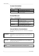
USER'S GUIDE____________________________________________________________________ Version Information Table 1 Manual Code U337EN-1.1 M210718EN-A M210718EN-B Manual Revisions Description December 1998 September 2005: EMC test data revised This manual, December 2009 - HUMICAP® sensor type has been changed.
Chapter 1 ________________________________________________________ General Information Feedback Vaisala Customer Documentation Team welcomes your comments and suggestions on the quality and usefulness of this publication. If you find errors or have other suggestions for improvement, please indicate the chapter, section, and page number. You can send comments to us by email: manuals@vaisala.
USER'S GUIDE____________________________________________________________________ - Always hold the boards by the edges and avoid touching the component contacts. Recycling Recycle all applicable material. Dispose of batteries and the unit according to statutory regulations. Do not dispose of with regular household refuse.
Chapter 1 ________________________________________________________ General Information Patent Notice The Vaisala HUMICAP® Humidity and Temperature Module HMM211 is protected by the following patents and patent applications and their corresponding national rights: Finnish patents 98861 and 99164, French patents 6650303 and 9504397, German patents 69418174 and 19513274, Japanese patents 3585973 and 2801156, UK patent 0665303, and US patent 5607564.
USER'S GUIDE____________________________________________________________________ b) the allegedly defective Product or part shall, should Vaisala so require, be sent to the works of Vaisala or to such other place as Vaisala may indicate in writing, freight and insurance prepaid and properly packed and labelled, unless Vaisala agrees to inspect and repair the Product or replace it on site.
Chapter 2 __________________________________________________________ Product Overview CHAPTER 2 PRODUCT OVERVIEW This chapter introduces the features and advantages of the Vaisala HUMICAP® Humidity and Temperature Module HMM211. Introduction to HMM211 The HMM211 modules are designed especially for relative humidity measurements in environmental chamber applications with high temperature and humidity levels. They also measure temperature and calculate the dewpoint temperature.
USER'S GUIDE____________________________________________________________________ temperature, and for the dewpoint module, the parameter is dewpoint temperature. The dewpoint temperature range can be either 0 ... +100 °C or -40 ... +100 °C. The probes also have a selectable chemical purge option. Note that with a warmed sensor head, the probe length is always 90 mm and the sensor is protected with a sintered filter. The HMM211 modules are connected to process control systems with screw terminals.
Chapter 3 ________________________________________ To Be Noted When Measuring Humidity CHAPTER 3 TO BE NOTED WHEN MEASURING HUMIDITY This chapter describes issues that need to be noted in the measurement of humidity. In the measurement of relative humidity and especially in calibration, it is essential that the temperature equilibrium is reached. Even a slight difference in the temperature between the measured object and the sensor causes an error.
USER'S GUIDE____________________________________________________________________ 10 9 8 dRH (%RH) 7 6 5 4 3 2 1 0 -40 -20 0 20 40 60 80 100 Temperature (°C) Figure 1 NOTE Measurement Error at 100 %RH when the Temperature Difference between the Ambient Air and the Sensor is 1 °C With a dewpoint module, the temperature equilibrium is not a problem as the temperature of the sensor head changes continuously and the sensor head has a fast humidity response.
Chapter 4 _______________________________________________________________ Installation CHAPTER 4 INSTALLATION This chapter provides you with information that is intended to help you install this product. Selecting Location Finding a suitable site for HMM211 is important for getting representative ambient measurements. Select a place that gives a true picture of the environment or process and is as clean as possible. Air should flow freely around the sensor.
USER'S GUIDE____________________________________________________________________ Dimensions 14 (0. 2 ) 1 6( .02 ) ~6 Figure 2 5(2 .56 ) Dimensions in mm (inches) Electrical Connections Connect wires according to Figure 3 on page 19 (A = voltage output, B = with current module).
Chapter 4 _______________________________________________________________ Installation 2 1 3 Figure 3 Electrical Connections The following numbers refer to Figure 3 above: 1 = During normal use, leave the jumper as indicated here (factory setting).
USER'S GUIDE____________________________________________________________________ This page intentionally left blank.
Chapter 5 _______________________________________________________________ Calibration CHAPTER 5 CALIBRATION This chapter provides you with information that is intended to help you calibrate this product. Vaisala recommends a recalibration of the HMM211 module after six months of use. After the first recalibration, the recommended calibration interval is approximately 12 months. However, please note that these intervals depend on the operating conditions and the required accuracy.
USER'S GUIDE____________________________________________________________________ One-Point Humidity Calibration With the Hand-Held Humidity and Temperature Meter HM70 or HMI41 Indicator and Calibration Cable You can calibrate the HMM211 module with the Hand-Held Humidity and Temperature Meter HM70 or HMI41 indicator and an appropriate calibration cable (for HM70: 27159ZZ; for HMI41: 19164ZZ). Connect the cable to the test connector of the HMM211 module and insert the jumper as indicated in Figure 4 below.
Chapter 5 _______________________________________________________________ Calibration The following numbers refer to Figure 4 above: 1 = For calibration with the HM70 or HMI41, insert the jumper as indicated here.
USER'S GUIDE____________________________________________________________________ information for Vaisala Service Centers on page 35. Figure 6 on page 27 illustrates the difference between offset and gain calibrations. Two-Point Humidity Calibration Procedure 1. 2. 3. 4. 5. 6. 7. 8. 9. Leave the calibrator and the probe in the same environment for at least one hour so that their temperatures have time to equalize.
Chapter 5 _______________________________________________________________ Calibration Figure 5 Calibration Pins and Pushbuttons With the jumper connected to the RH gain pins, each pressing of the UP or DOWN button changes the value approximately 0.05 %RH at 75 %RH. With the jumper connected to the RH offset pins, each pressing changes the value approximately 0.05 %RH. With the jumper connected to the T offset pins, each pressing of the UP or DOWN button changes the value 0.05 °C or 0.
USER'S GUIDE____________________________________________________________________ Temperature NaCl 4 ... 20 mA 0 ... 20 mA 0 ... 1 V 0 ... 5 V 0 ... 10 V *) °C °F %RH mA mA V V V 15 59 75.6 16.10 15.12 0.756 3.780 7.56 20 68 75.5 16.08 15.10 0.755 3.775 7.55 25 77 75.3 16.05 15.06 0.753 3.765 7.53 30 86 75.1 16.02 15.02 0.751 3.755 7.51 35 95 74.9 15.98 14.98 0.749 3.745 7.
Chapter 5 _______________________________________________________________ Calibration offset correction gain correction voltage range (for example, 0 ... 5 V) -20 20 Figure 6 3. before correction after offset correction 40 60 80 100 120 °C voltage range (for example, 0 ... 5 V) -20 20 before correction after gain correction 40 60 80 100 120 °C Offset and Gain Calibration Examples After having performed the calibration, disconnect the jumper.
USER'S GUIDE____________________________________________________________________ 2. 3. 4. 5. Allow enough time for the instruments to stabilize to the same temperature. Adjust the reading with UP and DOWN switches (see Figure 5 on page 25). Note that during gain adjustment, the offset point (-70 °C) does not change (see Figure 6 on page 27). Calibrate the additional (Ta) temperature probe the same way; note that the signal is on Channel 2 and the connectors used are the Ta offset and Ta gain.
Chapter 6 ___________________________________________________________ Chemical Purge CHAPTER 6 CHEMICAL PURGE This chapter provides you with information on chemical purge. In some applications, the sensor gain may decrease gradually due to an interference caused by some chemical present in the ambient air (see Figure 7 below). The sensor polymer absorbs the interfering chemical; this reduces the polymer's ability to absorb water molecules and so decreases the sensor gain.
USER'S GUIDE____________________________________________________________________ This page intentionally left blank.
Chapter 7 ______________________________________________________________ Maintenance CHAPTER 7 MAINTENANCE This chapter provides information that is needed in basic maintenance of the product. Replacing the HUMICAP180R Sensor and the Filter Remove the damaged sensor and insert a new one. Handle the sensor by the plastic socket. Recalibrate the transmitter. CAUTION Do not touch the sensor element. Replace a dirty filter to ensure a maximum lifetime and a fast response for the sensor.
USER'S GUIDE____________________________________________________________________ This page intentionally left blank.
Chapter 8 ___________________________________________________________ Troubleshooting CHAPTER 8 TROUBLESHOOTING This chapter describes common problems, their probable causes and remedies, and contact information for technical support.
USER'S GUIDE____________________________________________________________________ Return Instructions If the product needs repair, please follow the instructions below to speed up the process and to avoid extra costs to you. 1. 2. Read the section Warranty on page 11. Contact a Vaisala Service Center or a local Vaisala representative. The latest contact information and instructions are available from www.vaisala.com.
Chapter 8 ___________________________________________________________ Troubleshooting Vaisala Service Centers Vaisala Service Centers perform calibrations and adjustments as well as repair and spare part services. See contact information below. Vaisala Service Centers also offer accredited calibrations, maintenance contracts, and a calibration reminder program. Do not hesitate to contact them to get further information.
USER'S GUIDE____________________________________________________________________ This page intentionally left blank.
Chapter 9 ____________________________________________________________ Technical Data CHAPTER 9 TECHNICAL DATA This chapter provides the technical data of the product. Specifications Table 7 Relative Humidity Specifications Property Measurement range Accuracy (including non-linearity, hysteresis and repeatability) Value 0 ... 100 %RH ±2 %RH (0 … 90 %RH) ±3 %RH (90 …100 %RH) Response time (90 %) at +20 °C in still air 60 s (with sintered filter) Typical temperature dependence of 0.
USER'S GUIDE____________________________________________________________________ Figure 8 Dewpoint Temperature Table 9 Analog Output Specifications Property Two analog outputs selectable Typical accuracy Resolution Typical temperature dependence Table 10 Value 0 ... 1 V, 0 ... 5 V, 0 ... 10 V 0 ... 20 mA (4 ... 20 mA) ±0.1 % full scale CH1: 0.025 %RH CH2: 0.01 % full scale 0.
Chapter 9 ____________________________________________________________ Technical Data Table 11 Operating Voltage Specifications Ouput 0 ... 1 V 0 ... 5 V 0 ... 10 V 0 ... 20 mA (RL = 0 ) 0 ... 20 mA (RL = 500 DC 10 ... 35 V 14 ... 35 V 19 ... 35 V 10 ... 35 V 20 ... 35 V AC 9 ... 24 V 12 ... 24 V 16 ... 24 V 11 ... 24 V 17 ... 24 V ) NOTE AC supply only possible without warming or chemical purge option.
USER'S GUIDE____________________________________________________________________ Table 13 Cable Lengths for Sensor Heads Sensor Head Humidity sensor head Optional T sensor head/module with two sensor heads Table 14 Cable Length 65, 150, 300 cm 150 or 300 cm Automatic Chemical Purge Module RH and T module Dewpoint module RH and T module with two sensor heads Automatic Chemical Purge at Startup Yes Yes Yes 40 __________________________________________________________________ M210718EN-B
www.vaisala.