USER'S GUIDE Vaisala Radiosonde RS92-SGP M210295EN-H
PUBLISHED BY Vaisala Oyj Phone (int.): +358 9 8949 1 P.O. Box 26 Fax: +358 9 8949 2227 FIN-00421 Helsinki Finland Visit our Internet pages at http://www.vaisala.com/ © Vaisala 2012 No part of this manual may be reproduced in any form or by any means, electronic or mechanical (including photocopying), nor may its contents be communicated to a third party without prior written permission of the copyright holder. The contents are subject to change without prior notice.
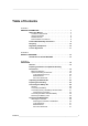
________________________________________________________________________________ Table of Contents CHAPTER 1 GENERAL INFORMATION . . . . . . . . . . . . . . . . . . . . . . . . . . . . . . . . . . . . . . 7 About This Manual . . . . . . . . . . . . . . . . . . . . . . . . . . . . . . . . . 7 Contents of This Manual . . . . . . . . . . . . . . . . . . . . . . . . . . . 7 Version Information . . . . . . . . . . . . . . . . . . . . . . . . . . . . . . . 8 Related Manuals . . . . . . . . . . . . . . . . . . .
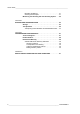
User's Guide ______________________________________________________________________ Releasing the Balloon . . . . . . . . . . . . . . . . . . . . . . . . . . . .41 Checking the Reception . . . . . . . . . . . . . . . . . . . . . . . . . . .41 Monitoring the Sounding with the Sounding System . . . .42 CHAPTER 4 STORAGE AND TRANSPORTATION . . . . . . . . . . . . . . . . . . . . . . . . . . . .43 Storage . . . . . . . . . . . . . . . . . . . . . . . . . . . . . . . . . . . . . . . . . .43 Transportation . .
________________________________________________________________________________ List of Figures Figure 1 Figure 2 Figure 3 Figure 4 Figure 5 Figure 6 Figure 7 Figure 8 Figure 9 Figure 10 Figure 11 Figure 12 Figure 13 Figure 14 Figure 15 Figure 16 Figure 17 Figure 18 Figure 19 Figure 20 Figure 21 Figure 22 Figure 23 Figure 24 Figure 25 Figure 26 Figure 27 Figure 28 Figure 29 Figure 30 Figure 31 Figure 32 Figure 33 Figure 34 Vaisala Radiosonde RS92-SGP . . . . . . . . . . . . . . . . . . . . . . .
User's Guide ______________________________________________________________________ 4 ___________________________________________________________________ M210295EN-H
________________________________________________________________________________ List of Tables Table 1 Table 2 Table 3 Table 4 Manual Versions . . . . . . . . . . . . . . . . . . . . . . . . . . . . . . . . . . . . . 8 Related Manuals . . . . . . . . . . . . . . . . . . . . . . . . . . . . . . . . . . . . . 8 Ordering Codes for Optional Sounding Accessories . . . . . . . . . . 20 RS92-SGP Battery Sets. . . . . . . . . . . . . . . . . . . . . . . . . . . . . . . .
User's Guide ______________________________________________________________________ 6 ___________________________________________________________________ M210295EN-H
Chapter 1 ________________________________________________________ General Information CHAPTER 1 GENERAL INFORMATION This chapter provides general notes for the manual and the product. About This Manual This manual provides information for operating Vaisala Radiosonde RS92-SGP. Contents of This Manual This manual consists of the following chapters: - Chapter 1, General Information: This chapter provides general notes for the manual and the product.
User's Guide ______________________________________________________________________ Version Information Table 1 Manual Versions Manual Code Description M210295EN-H M210295EN-G October 2012. This version. Updated for MW41. May 2010. Previous version. Contains RS92SGPL. October 2009.
Chapter 1 ________________________________________________________ General Information Documentation Conventions Throughout the manual, important safety considerations are highlighted as follows: WARNING Warning alerts you to a serious hazard. If you do not read and follow instructions very carefully at this point, there is a risk of injury or even death. CAUTION Caution warns you of a potential hazard.
User's Guide ______________________________________________________________________ Recycling Recycle all applicable material. Dispose of batteries and the unit according to statutory regulations. Do not dispose of with regular household refuse.
Chapter 1 ________________________________________________________ General Information License Agreement All rights to any software are held by Vaisala or third parties. The customer is allowed to use the software only to the extent that is provided by the applicable supply contract or Software License Agreement.
User's Guide ______________________________________________________________________ 12 __________________________________________________________________ M210295EN-H
Chapter 2 __________________________________________________________ Product Overview CHAPTER 2 PRODUCT OVERVIEW This chapter introduces the features and advantages of the radiosonde. Introduction to Vaisala RS92-SGP The digital Vaisala Radiosonde RS92-SGP offers excellent data availability, accuracy of humidity, pressure, temperature, and wind measurement. This radiosonde type features a GPS receiver for wind finding.
User's Guide ______________________________________________________________________ Figure 1 0705-015 Vaisala Radiosonde RS92-SGP 1 = GPS antenna 2 = Battery case 3 = Additional sensor interface connector 4 = Antenna 5 = Temperature sensor 6 = Humidity sensors 7 = Sensor boom 8 = GC25 interface Vaisala Radiosonde RS92-SGP can be used with Vaisala Sounding Systems MW41, MW32, MW31 and MW21, and with MW11, MW12, and MW15.
Chapter 3 ________________________________________________________________ Operation CHAPTER 3 OPERATION This chapter contains information that is needed to operate this product. General It is essential that you carry out the pre-launch steps as instructed and always in the same way. Follow the instructions in the sections below and refer to Appendix A on page 51 for proper and safe balloon preparation. The workorder for a sounding is as follows: 1.
User's Guide ______________________________________________________________________ Preparing the Balloon and Optional Sounding Accessories The balloon and the optional sounding accessories must be prepared before connecting the radiosonde battery and thereby activating the radiosonde. This is necessary because the radiosonde should be launched within 15 minutes of battery connection. WARNING Read the safety instructions in Appendix A before proceeding.
Chapter 3 ________________________________________________________________ Operation 2. Attach the balloon to the gas nozzle by securing the balloon with a piece of string or a clamp. Figure 3 0705-017 3. Attaching the Balloon to the Gas Nozzle Inflate the balloon following the balloon manufacturer’s inflation instructions. Do not leave the balloon-filling shed while inflating the balloon.
User's Guide ______________________________________________________________________ 4. When the balloon is sufficiently filled, in other words, the balloon just raises the gas nozzle, close the gas valve. Figure 5 0705-019 5. Balloon Raises the Gas Nozzle Secure the neck of the balloon tightly with a string before removing the balloon from the gas nozzle.
Chapter 3 ________________________________________________________________ Operation Figure 7 0705-021 6. Fold the neck of the balloon over and secure it firmly. Tie the string high enough to ensure that the unwinder fits easily. Figure 8 0705-022 7. Removing the Balloon from the Gas Nozzle Folding the Neck of the Balloon Leave the balloon waiting in the balloon-filling shed while you prepare the radiosonde. Make sure the balloon does not touch anything. Hold the balloon by the neck.
User's Guide ______________________________________________________________________ NOTE When using a balloon with an integrated parachute, make sure that a sufficiently long piece of the parachute string is poking out of the balloon neck in order to fasten the string to the radiosonde unwinder. Optional Sounding Accessories The RS92 unwinder RSU911 is designed to be attached directly to the folded balloon neck.
Chapter 3 ________________________________________________________________ Operation Radar Reflector Attach the unwinder to the radar reflector with a rubber plate accessory (Vaisala code RS46158). The rubber plate accessory lets the unwinder swing properly, making sure that the suspension string is unwound smoothly. 1. Tie the radar reflector to the balloon with a string of approximately 50 cm in length. 2. Attach the rubber plate (RS46158) to the radar reflector. See Figure 9 on page 22 for details.
User's Guide ______________________________________________________________________ Figure 9 Vaisala Radiosonde Sounding Accessories Option 1 = Sounding with a Totex parachute Option 2 = Sounding with no sounding accessories Option 3 = Sounding with a radar reflector Option 4 = Sounding with a non-Totex Parachute 0908-009 Now you can proceed to unpack the radiosonde.
Chapter 3 ________________________________________________________________ Operation Unpacking the Radiosonde Follow these steps to unpack the radiosonde: CAUTION Do not touch or hit the sensors on the sensor boom. Be careful not to bend the GPS antenna. By carefully handling the radiosonde and the sensor boom as well as the GPS antenna, you ensure that the radiosonde functions properly during the sounding. 1. Open the foil bag as indicated on the bag. Figure 10 0912-232 2.
User's Guide ______________________________________________________________________ Figure 11 0705-024 Contents of the Radiosonde Package 1 = Radiosonde 2 = Unwinder 3 = Battery 3. Remove the radiosonde from the package, free the antenna, and take the unwinder out of the package. 4. Remove the small plastic rubber wire from the unwinder. Figure 12 0601-048 Unwinder Details 1 = Rubber wire 2 = Unwinder lip 5.
Chapter 3 ________________________________________________________________ Operation Preparing the Sounding When preparing the sounding, Vaisala Ground Check Set GC25 is connected to the sounding system via cable and operated with the help of the sounding software. NOTE If you are using DigiCORA® Sounding System MW21, software version < 3.12, or MW15, MW12 or MW11, software version < 8.311, refer to the Ground Check Set GC25 User’s Guide for information on using the GC25 in the stand-alone mode.
User's Guide ______________________________________________________________________ 2. Connect the communication cable to the Ground Check Set interface in the radiosonde. Text "UP" on the connector faces upwards. Figure 14 0705-026 Radiosonde in the GC25 with the Communication Cable Connected 3. Switch on the PC and start a new sounding with the sounding system software. For detailed instructions, see the sounding system documentation. 4.
Chapter 3 ________________________________________________________________ Operation 6. CAUTION The back of the radiosonde facing you, press the sensor boom gently forward with your thumbs until the plastic clips on both sides click (you may have to spread the plastic clips slightly) and the sensor boom sits firmly in the bent position. Only touch the bottom of the boom. Do not touch or hit the sensors.
User's Guide ______________________________________________________________________ Connecting the Battery Set General RS92-SGP can be powered by the battery sets listed in Table 4 on page 28. See Figure 16 on page 28 and Figure 17 on page 29 for examples. The RS92-SGP ordering codes differ depending on the battery type. For instructions on using the Dry-cell Battery Set with switch with AUTOSONDE, see AUTOSONDE AS14 User’s Guide.
Chapter 3 ________________________________________________________________ Operation Figure 17 0705-030 RSB912P Water-activated Battery Connecting the Battery Follow these steps to connect the battery to the radiosonde: 1. Open the foil bag as indicated on the bag.
User's Guide ______________________________________________________________________ 2. Take out the battery connector (number 1 in Figure 19 on page 30) by gently pulling the wires. Figure 19 0912-140 3. Battery Connector Shown with RSB611 Connect the battery connector to the radiosonde. Figure 20 0705-039 Connecting the Battery Connector to the Radiosonde 4. The radiosonde has now been activated. Close the battery case. 5.
Chapter 3 ________________________________________________________________ Operation The radiosonde is now prepared for launch. In order to ensure 120 minutes of flight time, it is recommended that the radiosonde is launched within 15 minutes of battery connection. Proceed now to launch the radiosonde. Connecting the Dry-cell Battery Set with Switch Follow these steps to connect the Dry-cell Battery Set with switch: 1. Open the foil bag as indicated on the bag.
User's Guide ______________________________________________________________________ 2. Take out the battery connector by gently pulling the wires. Figure 22 0705-031 3. Battery Connector Take hold of the battery connector (number 1 in the following figures) and fold the wires to the side as shown in Figure 23 on page 32).
Chapter 3 ________________________________________________________________ Operation 4. Place the battery connector (1) onto the connector holder pins (2) of the battery case. The white pins (3) must face away from the batteries. Figure 24 Placing Battery Connector into Connector Holder, Part 2 CAUTION The white plastic pins must face away from the batteries, see Figure 24 on page 33.
User's Guide ______________________________________________________________________ 5. NOTE Connect the battery connector to the radiosonde, see Figure 25 on page 34. Make sure the battery connector stays connected into the connector holder all the time. If it becomes loose, battery activation will not work properly. Figure 25 0705-039 6.
Chapter 3 ________________________________________________________________ Operation 7. Press the red switch on the battery case to activate the battery. The green LED next to the red switch is lit, indicated with an arrow in Figure 27 on page 35. Make sure the LED stays lit. Figure 27 Green LED Light is Lit If the LED is not lit, see the instructions in section Checking the Connection on page 35. 8. Check from the sounding system software that the telemetry link is working well.
User's Guide ______________________________________________________________________ 31, making sure the connector is properly connected to the connector holder in the battery case. Connecting the Water-activated Battery NOTE Wear protective gloves when handling the Water-activated Battery. Follow these steps to connect the Water-activated Battery: 1. Open the foil bag as indicated on the bag. Figure 28 0705-028 2. Battery Package for Water-Activated Battery Take the battery out of its case.
Chapter 3 ________________________________________________________________ Operation 3. Place the battery in a water container with the connectors facing upwards and immerse in water for four minutes. Use fresh tap water, with a temperature of 15...25 °C. Figure 29 0705-040 Battery Immersed in Water 4. Take the battery out of the water after four minutes of immersion. Do not squeeze water out of the battery. 5. Put the battery back into the case.
User's Guide ______________________________________________________________________ 6. Connect the battery connector to the radiosonde. Figure 31 0705-039 Connecting the Battery Connector to the Radiosonde 7. The radiosonde has now been activated. Close the battery case. 8. Check from the sounding system software that the telemetry link is working well. For detailed instructions on using the sounding software, refer to the sounding system documentation. The radiosonde is now prepared for launch.
Chapter 3 ________________________________________________________________ Operation Removing the Battery Case If you need to remove the battery case from the radiosonde, use, for example, a small coin to loosen the battery case. Push the coin into the small opening between the radiosonde and the battery case to loosen the case and remove it. See Figure 32 on page 39. Figure 32 0809-005 Removing the Battery Case Launching the Radiosonde The radiosonde is now ready for launch.
User's Guide ______________________________________________________________________ needed to restrict the movement of the unwinder. For instructions, refer to section Optional Sounding Accessories on page 20. Attaching the Unwinder to the Balloon Follow these steps to attach the unwinder directly to the balloon: 1. Pass the unwinder hook through the loop created by the tied balloon neck. 2. Make sure that the hook comes out the other side, as shown in Figure 33 on page 40.
Chapter 3 ________________________________________________________________ Operation Totex Parachute The Totex parachute 5710-5 has an elastic ribbon loop below the spreader. Attach the unwinder to the loop by pushing the hook out the other side in the same fashion as with the folded balloon neck (see section Attaching the Unwinder to the Balloon on page 40). Radar Reflector There is a rubber plate attached to the radar reflector. Attach the unwinder to this plate.
User's Guide ______________________________________________________________________ Monitoring the Sounding with the Sounding System If you have not already done so, enter the surface observation information in the sounding system. Refer to the sounding system documentation for detailed instructions on using the sounding software.
Chapter 4 __________________________________________________ Storage and Transportation CHAPTER 4 STORAGE AND TRANSPORTATION This chapter provides information for the transport and storage of the product. Storage Radiosondes must be stored and used properly in accordance with applicable instructions, the User’s Guide, and specifications issued by Vaisala.
User's Guide ______________________________________________________________________ CAUTION The suspension string is not resistant to prolonged exposure to sunlight. Store the radiosondes in their original unopened vacuum envelopes. CAUTION When using the RSB511 or RSB521 Dry-cell Battery Set, we recommend that you store the radiosondes above +15 °C for at least two days before the sounding. If the radiosonde’s temperature before the sounding is close to 0 °C, the flight time may be compromised.
Chapter 4 __________________________________________________ Storage and Transportation - The package must display a lithium battery handling label, see Figure 34 on page 45 for an example. The original radiosonde shipping should be used for transport, and it already has the lithium battery handling label. - The consignment must include a document indicating the lithium content, describing proper handling and procedures for damaged packages, and a telephone number for additional information.
User's Guide ______________________________________________________________________ 46 __________________________________________________________________ M210295EN-H
Chapter 5 _________________________________________________ Failure Report and Warranty CHAPTER 5 FAILURE REPORT AND WARRANTY This chapter presents information about the failure report and radiosonde warranty. Technical Support For technical questions, contact the Vaisala technical support by e-mail at helpdesk@vaisala.com. Follow the instructions below to speed up the repair process and to avoid extra costs to you. 1. Read the warranty information. 2.
User's Guide ______________________________________________________________________ Product Returns NOTE RMA must always be requested from Vaisala technical support before returning any faulty material. If the product must be returned for service, see www.vaisala.com/ returns. For contact information of Vaisala Service Centers, see www.vaisala.com/services/servicecenters. Radiosonde Warranty The following Vaisala Radiosonde general warranty statement is effective as of 02/2007.
Chapter 5 _________________________________________________ Failure Report and Warranty Additional storage requirements for Vaisala AUTOSONDE: - the maximum number of days radiosonde can be loaded in AUTOSONDE is 24 - relative humidity below 50 % - temperature +15 °C to +35 °C Transportation and Handling Radiosondes shall be transported in the original shipping packaging, which is designed and built to survive and protect the contents in the environmental conditions specified in standard IEC 60721-3-
User's Guide ______________________________________________________________________ Making Warranty Claims A failure report shall be provided for each failed radiosonde stating the radiosonde serial number, a description of the failure, and sounding site and date. A template provided by Vaisala can be used for this. A radiosonde found defect prior to launch shall be returned to the nearest Vaisala office.
Appendix A _______________________________________ Safety Instructions for Balloon Operators APPENDIX A SAFETY INSTRUCTIONS FOR BALLOON OPERATORS This appendix contains details of safe and proper balloon preparation. Photocopy these instructions and place the list in clear view in the balloon-filling shed and in the sounding compartment. 1. No smoking or naked flame allowed. 2. If possible, avoid wearing clothing made of nylon or other synthetic fibers to prevent a build-up of static charges.
User's Guide ______________________________________________________________________ inflated balloon. The balloon film is only 0.05 ... 0.1 mm thick upon launch; the slightest scratch could cause the balloon to burst prematurely. 10. Keep the doors of the shed shut while inflating the balloon on a windy day. However, ensure that the shed is properly ventilated. 11. No unauthorized person shall be allowed admittance to the shed while the hydrogen generator is in operation or balloon inflation is going on.
____________________________________________________________________________ Index INDEX G A accessories activating the radiosonde attaching the unwinder 20 28 39 B balloon folding the neck 19 handling 16, 51 inflating 16 lifting gas 16 releasing 41 safety instructions 51 securing the neck 18 tying 18 balloon filling shed 16 battery connecting 28, 29, 31, 36 ordering codes 28 removing casing 39 RSB511 Dry-cell Battery Set 28, 44 RSB512 Dry-cell Battery Set with switch 31 RSB611 Lithium Battery 28 RSB912
User's Guide ______________________________________________________________________ P performing sounding preparations 25 R radar reflector radioactivity sounding radiosonde activating battery contents of the package features launching parts sensor boom storing transportation and handling unpacking warranty reception, checking reconditioning recycling releasing the balloon 21, 41 13 18 27 42 25 15 43 T 28 28 24 13 39 14 27 43 43 23 48 41 26 10 41 S safety instructions securing the balloon neck senso
www.vaisala.