
Operating instructions


VTM-98006F
8
SECTION 4
INSTALLATION
4-1 SITE INFORMATION. Valcom's VBBA 2-30 HF Antenna is designed primarily for
shipboard installation. The antenna can also be used at shore installations. The antenna
should be installed in a non-obstructed environment, clear from any contiguous
structures, such as masts, bulkheads, or other metal objects.
4-2 TOOLS AND MATERIALS REQUIRED. No special tools and materials are required for
installation.
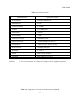
4-3 UNPACKING AND REPACKING. Table 1-2 gives data on the overall dimensions,
volume, and weight of the uncrated antenna. To unpack, carefully pry off the cover, and
remove the antenna from the container. Save the container to pack the antenna for
reshipment. No special handling procedures are required; observed normal precautions
when handling the antenna.
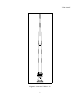
4-4 FOUNDATION. The antenna should be installed vertically on a mounting plate that has
bolt holes matching those in the antenna base (see figure 4-1).
4-5 INPUT REQUIREMENTS. The antenna has an rf power handling capability of 3 kW in
the 2 to 30 MHz frequency range.
4-6 INSTALLATION PROCEDURES. After unpacking the antenna, proceed with its
installation as follows:
a. Examine the exterior of the antenna for damage; make sure that the top of the lower
section and the bottom of the upper section has not been damaged, misaligned, or
fractured.
b. Before assembling the two sections together, the sleeve at top of the bottom section
must be coated with an electrically conducting compatible zinc base anti-seize compound
MIL-T-22361 (supplied).
c. Place the bottom section of the antenna on two saw horses. After applying the anti-
seize compound to the mating sleeve, carefully slide the antenna top section over the
sleeve making sure the arrows on each section are aligned.
d. Ensure the eight holes are in line between the two sections. Install the eight
countersink flat head screws to the two sections. After installation, seal the screw heads
and the antenna joint using the insulating compound.