
Operating instructions


VTM-98006F
9
e. Carefully lift the antenna to its mounting platform. Align the mounting holes of the
base flange with the mounting holes in the platform.
f. Secure the antenna to its mounting plate with using eight 5/8-11 hex head cap screws,
flatwashers (two per bolt required), split lockwashers and nuts. Bolt length will be
determined by the installing activity.
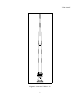
g. Make sure the ground strap supplied with the antenna is connected to one of the
mounting bolts directly below the input connector on the antenna as shown in Figure 4-1.
h. The VBBA 2-30 antenna input is an 7/8 EIA Flange and is found on the base insulator
below the drip shields. Prior to connecting the system feedline, ensure the equipment has
been de-energized and proper lock out procedures followed. Once the lockout
procedures have been performed, connect the system feedline to the antenna. For 1 kW
operation with the antenna, an 7/8 EIA to N Adapter can be supplied for connecting to an
N type feedline cable connector. For more than 1 kW operation, a 7/8 EIA Flange can be
supplied for the feedline used. Ensure the ground wire supplied has a secure connection
at the input connector on one end and the other end to the antenna mounting bolt. Seal
the ground connection at both ends using the insulation compound provided.
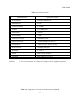
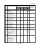
4-7 CABLES AND CONNECTORS. Other types of cables and connectors can be used to
connect the antenna’s input connector to the radio equipment. Some suggestions can be
found in table 4-1.
Table 4-1 Cable and Connector Group Suggestions
Group 1
(Heliax Cable)
Cable: LDF4-50A (Andrew)
(½" Dia., 50 S, 3 kW @ 30 MHz)
Connector: 7/8 EIA Flange L44R (Andrew)
Group 2
(Heliax Cable)
Cable: LDF5-50T (Andrew)
(7/8" dia., 50 S, 14 kW @ 30 MHz)
Connector: 7/8 EIA Flange L45R (Andrew)
Group 3
(1kW)
Cable: RG-214/U
Connector: N-type UG-21E/U
4-8 INSTALLATION CHECKOUT. Checkout of the antenna after installation can only be
accomplished by operating the receiving and transmitting equipment that is used with the
antenna.