
Manual

PAGE 2
Install inlet and outlet shutoff valves to facilitate replacement
of elements. By-pass piping is recommended.
Check labels on lter housing, and connect piping so that air
ows through inlet and outlet ports as indicated. Make sure
air ow through lter element is correct. Improper ow direc-
tion can minimize lter performance. (See Table 2).
Install differential pressure gauge (optional) on lter housing
using instructions provided with gauge kit. Differential pres-
sure is used to monitor element life (except grade RD) and
indicates when an element change is required.
(See Table 6).
Locate compressed air and gas lters at the point of lowest
operating temperatures to ensure that water and oil vapor will
not condense downstream of the lter.
Filters should be installed close to the point of use to mini-
mize the risk of pipe scale, dirt, etc. recontaminating the
compressed air or gas. This is particularly important when
installing new lters on an existing installation which has not
had proper ltration.
Protect lters from reverse ow conditions. Do not install
lters downstream of quick opening valves.
Before installing lter check ambient and operating tempera-
ture and pressure conditions to verify that they are within the
specied ranges. (See Table 1). Also verify that system ow
rate corresponds to the rated capacity of the lter. (See Table
4). Operating lter at ows above rated capacity will result in
increased pressure drop. Do not use reducers to match lter
inlet size. The resulting restriction will cause high pressure
drop.
Install lter in vertical position. Provide required minimum
clearance below lter to allow for replacement of elements.
(See Table 3).
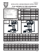
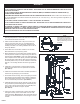
FIGURE 2 TYPICAL ASSEMBLY
FIGURE 1 LONG FLANGE BOLT (Element access)
WARNINGS
1.
2.
3.
4.
5.
INSTALLATION (PART 1 FILTER HOUSING)
6.
7.
8.
DO NOT REMOVE, REPAIR OR REPLACE ANY ITEM ON VESSEL WHILE IT IS UNDER PRESSURE.
DO NOT OPERATE IF THERE IS A LEAK IN VESSEL. TAKE VESSEL OUT OF SERVICE IMMEDIATELY AND NOTIFY YOUR
CERTIFYING AUTHORITY.
DO NOT OPERATE ABOVE MAXIMUM WORKING PRESSURE (MWP) AT MAXIMUM OPERATING TEMPERATURE (°F)
SHOWN ON ASME NAMEPLATE.
THIS ASME CODE VESSEL MUST BE PROTECTED BY A PRESSURE RELIEF VALVE. Refer to OSHA 1910.169 Par b, Sub
Par (3) and ASME Boiler and Pressure Vessel Code, Section VIII, Div 1 UG-125, Par (1). Also check government regulations, i.e.,
state and local codes.
DO NOT WELD, GRIND OR SAND VESSEL. IT WILL NOT BE SAFE TO OPERATE.
DO NOT OPERATE VESSEL IF THERE HAS BEEN A FIRE. TAKE VESSEL OUT OF SERVICE IMMEDIATELY AND NOTIFY
YOUR CERTIFYING AUTHORITY.
ANY DAMAGE TO VESSEL CAN MAKE IT UNSAFE. INSPECT OUTSIDE AND INSIDE OF VESSEL REGULARLY FOR COR-
ROSION OR ANY DAMAGE (i.e., DENTS, GOUGES OR BULGES). IF DAMAGED OR CORRODED TAKE OUT OF SERVICE
IMMEDIATELY AND NOTIFY YOUR CERTIFYING AUTHORITY.
USE THE PROPER RULES FOR THE GAS BEING PROCESSED.
Insert close nipple in threaded hole on bottom blind ange
and tighten securely. Screw manual drain valve on close
nipple and tighten. (See Figure 2). When automatic draining
is required, a motorized ball valve or solenoid type is recom-
mended.
9.
NOTE
Vessel models F101-500 thru
F101-2000 are equipped with a
single long ange bolt to permit
rotating of blind ange for access
to elements.