
Manual

PAGE 3
Element(s) are shipped separately and must be in-
stalled before lter is ready for service. Remove hex
fasteners(s) from tie rod(s) in housing.
Remove element(s) from packaging and remove o-ring(s)
from bottom end cap(s) of element(s). Install o-ring(s) in o-
ring groove(s) on hex fastener(s). (See Figure 2).
Install element(s) in housing so that the tie rod protrudes
through small hole in bottom end cap.
Thread hex fastener(s) onto the tie rod(s) and tighten so that
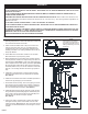
Provide support under blind ange to prevent it from falling
when bolts are removed. Blind anges are heavy and could
cause injury if allowed to fall.
(See Table 3 for blind ange weights).
Remove bolts from ange and lower blind ange for access
to elements. Filter models F101-500 through 2000 are
equipped with a single long ange bolt to permit rotation of
blind ange for access to elements. (See Figure 1).
Before closing housing, inspect bafe to make certain that
new elements have been installed in each position.
(See Table 5 for element replacement data).
With gasket in place, carefully raise or swing blind ange
into place and align bolt holes. Insert all bolts and complete-
ly tighten all nuts evenly.
Close drain valve; then slowly open inlet and outlet valves.
Close by-pass valves if provided.
Filter is now in service.
INSTALLATION (PART 2 ELEMENT)
7.
8.
9.
10.
Drain oil removal lters every shift.
Check differential pressures regularly on coalescing and
particulate lters (AA, A, B, C, RA, RB, RC, and HT grades).
When differential pressure reaches 10 psid, install clean ele-
ments. On adsorbing lters (grade RD), install clean elements
when hydrocarbon vapors are rst detected downstream or
every six months, whichever comes rst.
For correct replacement element model numbers, see label on
lter housing and/or the bottom endcap of the element.
(Refer to Table 5).
•
•
•
MAINTENANCE
the element(s) are held rmly in place. Do not over tighten.
(See Figure 2).
DO NOT LOOSEN FLANGE BOLTS BEFORE THE VES-
SEL HAS BEEN COMPLETELY DEPRESSURIZED.
WARNING
6.
3.
4.
5.
1.
2.
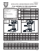
FILTER
MODEL NO.
F101-500-(*)
F101-1000-(*)
F101-1500-(*)
F101-2000-(*)
F101-3500-(*)
F101-5000-(*)
*Insert appropriate ltration grades here; for example F101-3500-C and
replacement element E101/102-625-C (ve required).
TABLE 5 REPLACEMENT PARTS
REPLACEMENT PARTS
REPLACEMENT
ELEMENT MODEL
NUMBER
E101/102-500-(*)
E101/102-500-(*)
E101/102-500-(*)
E101/102-625-(*)
E101/102-625-(*)
E101/102-625-(*)
ELEMENT
WEIGHT
LBS
2.8
2.8
2.8
3.2
3.2
3.2
NUMBER OF
ELEMENTS IN
HOUSING
1
2
3
3
5
8
HOUSING
GASKET
18-0207
18-0206
18-0210
18-0210
18-0209
18-0211
MANUAL DRAIN
VALVE
14-0450
14-0450
14-0450
14-0450
14-0450
14-0451
PART
NUMBER
29-0370
29-0371
84-0129
84-0131
84-0130
84-0211
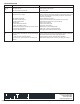
TABLE 6 DIFFERENTIAL PRESSURE GAUGE KITS:
ACCESSORIES
MODEL NUMBER
PD-2 GAUGE
PD-2/SW GAUGE
PD-2 KIT
PD-2/SW KIT
PD-2/HT KIT
PD-2/HT SW KIT
DESCRIPTION
Differential pressure gauge. (Only)
Differential pressure gauge with N.O. reed switch. (Only)
Differential pressure gauge with nylon tubing and brass tube ttings.
Differential pressure gauge with N.O. reed switch, nylon tubing and brass tube ttings.
Differential pressure gauge with stainless steel tubing and steel tube ttings (for HT units).
Differential pressure gauge with N.O. reed switch, stainless steel tubing and steel tube ttings (for HT units).
HEX
FASTENER
26-3258
26-3258
26-3258
26-3258
26-3258
26-3258