INSTALLATION & OPERATION MANUAL DO NOT DISCARD THIS MANUAL! POWERMAX tm GAS INFRA-RED WATER BOOSTER HEATERS Model PM200 and PM400 IMPORTANT FOR YOUR SAFETY WARNING: IF THESE INSTRUCTIONS ARE NOT FOLLOWED EXACTLY, FIRE OR EXPLOSION MAY RESULT, CAUSING PROPERTY DAMAGE, PERSONAL INJURY OR DEATH. -Do not store or use gasoline or any other flammable liquids or vapors in the vicinity of this or any other appliance.
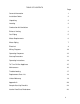
TABLE OF CONTENTS Page General Information 1 Installation Codes 2 Unpacking 2 Locating 2 Combustion Air/Ventilation 3 Exhaust Venting 3 Gas Piping 5 Water Requirements 6 Water Piping 7 Electrical 9 Wiring Diagrams 10 Operating Sequence 12 Start-up Procedure 13 Operating Instructions 14 To Turn Off Gas Appliance 15 Maintenance 16 Troubleshooting 17 Replacement Parts List 18 Limited Warranty 19 Appendix A 20 Sample Start Up Checklist 24 Interior View/Parts Breakdown
GENERAL INFORMATION The POWERMAXtm gas fired, infra-red water booster heater provides 180 degree sanitizing rinse water for commercial dishwashing machines. Dishware and utensils used in the preparation and serving of food are required by Health Codes and the National Sanitation Foundation (NSF) to be sanitized by hot (min. 180 degrees Fahrenheit) water or a chemical sanitizing solution to destroy bacteria and parasitical organisms.
INSTALLATION CODES Installation must be performed in accordance with state and local codes, or, in the absence of local codes, with the following: National Fuel Code, ANSI Z223.1 (latest edition) the National Electric Code (NEC) ANSI/NFPA 70 (latest edition). Canada: CAN/CGA B149.1, CAN/CGA B149.2 and CSA C22.2 No. 1 (latest edition). UNPACKING Immediately after unpacking, check thoroughly for any possible shipping damage.
COMBUSTION AIR / VENTILATION The POWERMAXtm must be provided with an adequate supply of air for proper combustion and ventilation as required by the National Fuel Gas Code, ANSI Z 223.1 or any local codes that supercede the National Code. Do not obstruct the combustion and/or ventilation air supply openings. CAUTION: Combustion air must not be contaminated by corrosive vapors or fumes, i.e. salt, chlorine, refrigerant gases, detergents, paints, cleaners, etc..
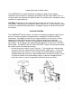
2. Through the ceiling/roof (see fig.3) or through a sidewall (see fig. 4). Type B-1 vent pipe (inch min. diameter) may be used when venting vertically through the roof, provided a one inch minimum clearance to combustible material is maintained throughout and the vent terminates into a listed wind cap above the roof. 3. Vented freely into the room or space where it is installed, provided that: a) A Mechanical exhaust system is present in the space where the booster heater is installed.
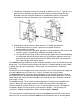
any door, opening window or gravity air inlet into any building. It shall also have a minimum horizontal clearance of four feet from any electric meter, gas meter, regulator, relief valve or other equipment. -The vent terminal shall be located not less than seven feet above grade when it is adjacent to public walkways. -The bottom of the vent terminal shall be located at least twelve inches above grade or ground or the normally expected snow accumulation level.
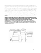
The gas valve is provided with a pressure tap to measure gas pressure downstream, which is also the manifold pressure (fig. 5.). The gas piping must have a sediment trap ahead of the heater gas controls and an approved manual shut-off valve (provided by others) located outside the jacket and easily accessible. The heater and its gas connections must be leak tested before placing the appliance in operation. DO NOT use an open flame for leak testing.
Recommended water hardness is 4-6 grains of hardness per gallon. Chlorides must NOT exceed 50 parts per million. Water hardness above 6 grains per gallon should be treated with a proper water conditioner (water softener or in-line treatment). Water hardness below 4 grains per gallon also requires water treatment to reduce its corrosive effects. Sediment, silica, chlorides or other dissolved solids may require particulate filtration or reverse osmosis treatment.
Follow instructions on the tag located on the Temperature and Pressure Relief valve to avoid contact with hot water discharge and to prevent water damage from operation of the valve. Repair or alteration of the Temperature and Pressure Relief valve in any way is prohibited by National Safety Standards and local codes.
ELECTRICAL The electrical power supply requirement for the booster heater is 120 volts, AC, 60Hz, 6.0 amps or less. Field wiring connections and electrical grounding must comply with local codes, or, in the absence of local codes, with the latest edition of the National Electric Code (NEC), ANSI/NFPA 70. NOTE: Polarity must be observed for the booster heater to operate properly. Consult wiring diagram.
10
11
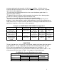
OPERATING SEQUENCE The booster heater is designed to produce 180-190 degree sanitizing rinse water for commercial dishwashing machines. Specific performance depends upon the exact water flow and supply water temperature. (See table) PowerMax200tm Performance Data Temperature rise 40o F 50o F 60o F 70o F 140o F Gallons per Minute Gallons per Hour 8.7 520 7.0 420 5.8 348 5.0 300 2.5 (7.5 for 15 sec.
POWERMAXtm START-UP PROCEDURE For your safety, read completely before operating. CAUTION: DO NOT turn Power Switch ‘on’ until the booster has been filled with water and all air has been purged from the water lines and accumulator tank. FILL THE BOOSTER HEATER Open the water supply valve at the Booster Heater water supply inlet and fill Booster Heater. Manually open the temperature/pressure relief valve on the left side of the cabinet to vent air from water piping.
FOR YOUR SAFETY, READ BEFORE OPERATING WARNING! - IF YOU DON’T FOLLOW THESE INSTRUCTIONS EXACTLY, A FIRE OR EXPLOSION MAY RESULT CAUSING PROPERTY DAMAGE, PERSONAL INJURY OR DEATH. A. This appliance DOES NOT have a standing pilot ignition system. It is equipped with a hot surface ignition device that automatically lights the burner. DO NOT attempt to light the burner by hand. B. Before starting the appliance, smell all around the appliance area for gas odor.
TO TURN OFF GAS TO APPLIANCE 1. Turn off all electric power to the booster heater if service is to be performed. 2. Turn off manual gas valve in gas supply piping. 3. Remove front access panel by lifting panel to release bottom, tilting panel away from unit and removing panel. 4. Push in and turn gas control knob clockwise 5. Replace front access panel. to the ‘OFF’ position.
MAINTENANCE Lubrication The water pump motor and the combustion air blower are permanently lubricated and require no periodic maintenance. Auxiliary power vent motor (depending upon model) may or may not need periodic adjustment or lubrication. Consult power vent manual. Vent System Check the vent system annually for damage and/or obstruction. Any deformation of the vent system should be examined carefully to determine the cause of the deformation.
TROUBLE SHOOTING CAUTION: Label all wires prior to disconnection when servicing controls. Wiring errors can cause improper and dangerous operation. Verify proper operation after servicing. PROBLEM CAUSE REMEDY 3. On-Off switch powered, Unit does not operate. a. No power to heater. b. Manual reset Hi-limit tripped. c. Vent fan interlock not proving (if auxiliary power vent or E-Z Vent system) is being used. a. Check circuit breaker b. Manually reset hilimit. Determine cause.
REPLACEMENT PARTS LIST When ordering parts, always refer to the Model number and Serial Number. The data plate is mounted on the electrical panel face behind the front cover panel. NOTE- Part numbers may change without notification. To obtain the most recent part numbers contact the Factory or your authorized Vanguard service agency. Model PM200, 199,900 BTU/Hr. & Model PM400, 399,800 BTU/Hr.
LIMITED WARRANTY: Products manufactured by Vanguard Technology. Inc.
APPENDIX A TYPICAL SPECIAL STAINLESS STEEL VENTING For use with Category II, III, IV appliances Contact Local Building or Fire Officials About Restrictions and Installation Inspections in your area as well as National codes: USA -National fuel gas code ANS1-Z223.l CANADA -CAN\CGA-B 149.1 or .
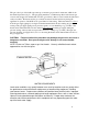
Appendix A JOINT PROCEDURE (see illustration #1 below) 1. The outside of male end and inside of female end of pipe must be cleaned before applying silicone bead. Remove dirt, grease, and moisture from surface to be sealed. Dry surface or allow to dry thoroughly. 2. Apply high temperature silicone approximately one half inch from end around male end of pipe and along both sides of seam for one inch in an even 1/4” bead as per illustration #1. 3. Pipes can now be pushed together as far as they will go.
Appendix A SIDE WALL VENTING INSTALLATION SIDE WALL VENTING INSTALLATION (see illustration #2) 1. Install wall thimble into wall, observing the aforementioned rules and/or local building codes. Select the point of wall penetration where the minimum 114” per foot of slope (6.4 mm per 305 mm) can be maintained. The pipe can be located between joists spaced 16” (400 mm) on centre. The pipe may be mortared in directly without using a wall thimble, if the wall is non-combustible.
Appendix A 3. The system must be supported along its horizontal length at all elbow locations and joints (every fortyeight inches or less) using straps around pipes maintaining clearance to combustibles as per table. Any horizontally installed portion of a venting system shall have a slope (upwards for Category II, III, or IV appliances or (upwards for Category Ill or IV appliances) not less than 1/4” (6.4 mm) every 12 inches (305 mm) to prevent collection of condensate at any location in the assembly.
2 9 4 9 5 A ir p o r t R o a d , E u g e n e , O R 9 7 4 0 2 T e l:( 5 4 1 ) 4 6 1 - 6 0 2 0 F a x :(5 4 1 ) 4 6 1 - 6 0 2 3 T o ll F r e e : 1 - 8 0 0 - 6 2 4 - 4 8 0 9 Factory Authorized PowerMax Start-Up Verification Worksheet Job Name:______________________________________________________________ Job Location:____________________________________________________________ Dealer Name: ! ! ! ! ! ! ! ! ! ! ! ! ! ! ! ! ___________ Serial # ___________________ Verify incoming water temperature to booste
Page 2 Vanguard Technology Inc. Factory Authorized Start-Up - Verification Worksheet - continued ! ! ! ! ! Bleed air from accumulator and heat exchanger through temperature/pressure relief valve. Turn power switch ‘on’. Burner(s) will activate until accumulator temperature setting is reached. Output temperature sensor should reduce burner to low flame shortly before burner shuts off. When unit is at temperature, flush approx. 25 gal. of hot water through the unit before shutting off.
26