
Water Heater User Manual

5
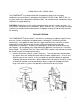
any door, opening window or gravity air inlet into any building. It shall also have a
minimum horizontal clearance of four feet from any electric meter, gas meter, regulator,
relief valve or other equipment.
-The vent terminal shall be located not less than seven feet above grade when it is
adjacent to public walkways.
-The bottom of the vent terminal shall be located at least twelve inches above grade or
ground or the normally expected snow accumulation level.
The snow level may be higher on walls exposed to prevailing winds.
-Avoid areas where local experience indicates that condensate drippage may cause
problems, such as above planters, patios, public walkways or areas where condensate or
vapor could cause a nuisance or hazard, or where its discharge could be detrimental to the
operation of regulators, relief valves or other equipment.
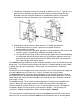
Examples of ACCEPTABLE VENT PIPING/ See Appendix A
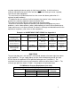
MANUFACTURER MODEL MATERIAL
SPECIFICATION
Part Name
3”
Part Number
4”
Part Number
Heat-Fab Inc.
38 Haywood St.
Greenfield, MA 01301
Saf-T-Vent AL 29-4C
Stainless Steel
Tee
Rain Cap
Mitre I Straight
7390TEE
5300C1
7390GC
7490TEE
5400C1
-
Z-Flex US, Inc.
20 Commerce Park North
Bedford, NH 03110
Z-Vent AL 29-4C
Stainless Steel
Tee
Rain Cap
Termination Box
#02SVSTTX-3
#02VRSRCX03
#02SVSRTX-3
#02SVSTTX-4
#02VRSRCX04
#02SVSRTX-4
Flex-L International, Inc.
6385 Kennedy Rd
Mississauga, ON
L5T2W4
StaR-34 AL 29-4C
Stainless Steel
Termination Tee
Wall Thimble
SRTT03
SRWT153
SRTT04
SRWT154
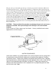
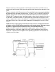
GAS PIPING
The gas inlet pipe size is 3/4 inch NPT, male thread, located at the lower right front corner
of the appliance. The gas supply piping must be sized to adequately provide the input
BTU/hr rate for the appliance at the specified flowing pressure (see table 1). The
maximum inlet gas pressure must not exceed the maximum value shown in table 1. The
minimum gas pressure shown in Table 1 is for purposes of input adjustment.
FLOWING Gas Pressure Requirement (not static)
Inches W.C. (Water Column)
Incoming Line Pressure Natural Gas/LP
Minimum Maximum
Manifold
Pressure
PM200 4.5”NG/10”LP 10.5”NG/14”LP 3.5”NG/7.5”LP
PM400 4.5”NG/10”LP 10.5”NG/14”LP 3.5”NG/7.5”LP
TABLE 1