OPERATING INSTRUCTIONS for Models ATRT-01, ATRT-01B, and ATRT-01D Single Phase Transformer Turns-Ratio Meter Vanguard Instruments Co., Inc. 1710 Grevillea Court Ontario, California 91761 TEL: 909-923-9390 FAX: 909-923-9391 May 2002 REV.
Model ATRT-01 (v) Operating Instructions NOTICE This manual applies to Models ATRT-01, ATRT-01B, and ATRT-01D; the operating procedures are virtually the same for all models; any differences, which relate to the test units’power sources, are clearly described within the step-by-step procedures. SAFETY WARNINGS AND CAUTIONS This device shall be used only by trained operators. All transformers under test shall be off line and fully isolated Do not Service or Test alone.
Model ATRT-01 (v) Operating Instructions Table of Contents 1.0 Introduction ............................................................................................................................4 2.0 Applicability ...........................................................................................................................4 3.0 Operating Configuration .........................................................................................................4 4.0 Principle of Operation ....
Model ATRT-01 (v) Operating Instructions List of Tables Table 5-1. Model ATRT-01 (v) Turns-Ratio Meter Specifications .................................................5 Table 5-2: ATRT-01, ATRT-01B, and ATRT-01D Cable Set .........................................................6 Table 6-1. Cable Markings and Identification .................................................................................6 Table 25-1. Single-Phase Transformer Test Procedure. .................................................
Model ATRT-01 (v) Operating Instructions 1.0 Introduction The Model ATRT-01 is a microprocessor-based, field-portable, automatic, transformer, turnsratio test meter designed for on-site measuring of: turns ratios, winding polarity, and no-load excitation currents of single and 3-phase utility transformers. The ATRT-01 can also test potential transformers (PTs) and primary current transformers (CTs). The ATRT-01 may not test some types of donut transformers (i.e.
Model ATRT-01 (v) Operating Instructions 4.0 Principle of Operation The ATRT-01 measures transformer turns ratio by applying a test voltage across the (H) winding and sensing induced voltage on the secondary (X) winding. (For safety, testing is always done in a step-down transfer, regardless of the transformer’s actual use.) There's no load on windings during testing, so measured voltage ratio is virtually the same as the winding turns ratio. The ATRT-01 measures turns ratios in a range from 0.8 to 15,000.
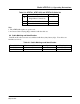
Model ATRT-01 (v) Operating Instructions Table 5-2: ATRT-01, ATRT-01B, and ATRT-01D Cable Set Item Description 1 Test-Lead Cable, 15-foot Single-Phase Connections Power Cord (Note 1) RS-232C Cable 2 3 Qty 1 1 1 Note: 1. The ATRT-01D requires no power cord. 2. A Canvas Cable-Carrying Bag is included with the cable set. 6.0 Cable Marking and Identification: Both H and X cable test leads are terminated with heavy-duty battery clips. Test cables are identified as follows: Table 6-1.
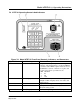
Model ATRT-01 (v) Operating Instructions 7.0 ATRT-01 Operating Controls And Indicators Figure 7-0. Model ATRT-01 Front-Panel Controls, Indicators, and Connectors Fig. 7-0 Index 1 Panel Markings Functional Description RS-232C Computer-Interface port, 9-pin, female DB type connector; RS-232C interface port allows ATRT-01 to interface with an IBM computer. Data rate is set to 19,200 baud, 1 start bit, 8 data bits, 2 stop bits, and no parity bit.
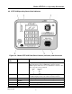
Model ATRT-01 (v) Operating Instructions 8.0 ATRT-01B Operating Control And Indicators Figure 8-0. Model ATRT-01B Front-Panel Controls, Indicators, and Connectors Fig. 8-0 Index Panel Markings Functional Description 1 RS-232C 2 None (display) 3 4 None (H & X) 120/220Vac, 1A, 50/60Hz Computer-Interface port, 9-pin, female DB type connector; This RS-232C interface allows ATRT-01B to interface with an IBM computer.
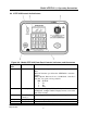
Model ATRT-01 (v) Operating Instructions 9.0 ATRT-01D Control And Indicators Figure 9-0. Model ATRT-01D Front-Panel Controls, Indicators, and Connectors Fig. 9-2, Index 1 Panel Markings Functional Description RS-232C Computer-Interface port, 9-pin, female DB type connector; This RS-232C interface port allows the ATRT-01D to interface with an IBM computer. Data rate is set to 19,200 baud, 1 start bit, 8 data bits, 2 stop bits, and no parity bit.
Model ATRT-01 (v) Operating Instructions 10.0 ATRT-01 Power Switch Configurations 10.1 ATRT-01 Power Turn On/Off The ATRT-01 is powered by ac line voltage only. The power is turned on and off with a power switch that is built into the power receptacle (see item 4 of Figure 7-0). 10.2 ATRT-01B Power Turn On/Off The ATRT-01B is turned on or off by pressing POWER (see item 6 on Figure 8-0), on the front panel, for 2 seconds, then releasing the switch. 10.3.
Model ATRT-01 (v) Operating Instructions 15.0 ATRT-01 Battery replacement 15-1. ATRT-01B Battery Replacement Replace the ATRT-01B battery with the following: Panasonic part number LC-R122R2PU. Note A rechargeable lead-acid battery powers the ATRT-01B. A fully charged ATRT-01B can be continuously operated for 6 hours. A built-in charger lets the unit to be used during charging. Plugging the ATRT-01B into an ac power outlet after the battery is fully charged will not damage the battery.
Model ATRT-01 (v) Operating Instructions 16.0 DISPLAY and MENU DESCRIPTIONS This section describes the operating menus of the ATRT-01. 16-1 Start-Up Menu 1. TEST XFMR 04/12/00 2. SETUP 13:06:02 3. CALCULATOR Figure 16-0 Start-up menu a. Description: The start-up menu lets the user test a transformer, set-up time, select computer interface, or use the calculator to manually enter voltage data for transformer ratio calculation. b. Origin: The Start-up menu first displays after power is applied to ATRT-01. c.
Model ATRT-01 (v) Operating Instructions Figure 16-1 ATRT-01 Menu Diagram Rev 02 May 02, 2002 13
Model ATRT-01 (v) Operating Instructions Rev 02 May 02, 2002 14
Model ATRT-01 (v) Operating Instructions 17.0 Test Transformer Selection XFMR CONFIGURATION: 1.SNGL PHS 2.dT-Y 2.Y-dT 4.dT-dT 5.Y-Y Figure 17-0 Transformer Selection menu a. Description: This menu allows the user to select a particular transformer to be tested. If the user selects a three-phase transformer, the ATRT-01 will display hookup instructions (ATRT-01 cables to the transformer terminal bushing) for phases A, B, and C. b.
Model ATRT-01 (v) Operating Instructions 18.0 Transformer Voltage Selection XFMR NAME PLATE VLTG 1. YES 2. NO Figure 18-0. Nameplate Voltage Selection Menu a. Description: This menu allows the operator to use the transformer nameplate voltages to derive a calculated turns ratio. This calculated turns ratio is then used to compare with the measured turns ratio, which produces an error-difference percentage. b. Origin: This menu is displayed after the operator selects the transformer type to be tested. c.
Model ATRT-01 (v) Operating Instructions 19.0 Transformer Voltage Data Entry Menu ENTER H WINDING NAME-PLATE VOLTAGE: V Figure 19-1. H-Winding Voltage Entry Display ENTER H WINDING NAME-PLATE VOLTAGE: 7200V Figure 19-2. H-Winding Voltage Entry Display ENTER X WINDING NAME-PLATE VOLTAGE: V Figure 19-3. X-Winding Voltage Entry Display ENTER X WINDING NAME-PLATE VOLTAGE: 480V Figure 19-4.
Model ATRT-01 (v) Operating Instructions a. Description: This menu allows the user to enter the H and X voltages of the transformer to be used in the turns-ratio calculation. The user must enter the transformer nameplate line voltages. b. Origin: H and X voltage data entry menu will appear if the user select YES (key #1) on the Voltage-selection screen (see Figure 18-0). c. Action Option: Press keys 0 thru 9 to enter transformer voltages. Press ENTER to confirm voltage entry.
Model ATRT-01 (v) Operating Instructions 20.0 Start Test Menu SINGLE PHASE XFORMER “START” TO RUN TEST OR “STOP” TO ABORT Figure 20-0. Start Test Screen a. Description: This menu allows the user to start or abort a test. b. Origin: After the user enters the nameplate voltages (see Figure 19-4) or selects NO on the “XFMR NAME PLATE VLTG Screen” (see Figure 18-0). c. Action Option: Press START to start the test and press STOP to abort the test.
Model ATRT-01 (v) Operating Instructions 21.0 Transformer Turns-Ratio Test Result Display RATIO +1.003 mA 0002 %DIFF 0.3 Figure 21-0. Test Result Display a. Description: The ATRT-01 displays the transformer turns ratio, excitation current (in milliamps), and turns-ratio error percentage. A typical turns-ratio test-result screen is shown on Figure 21-0, above. Note Ratio displayed: 1.003 Polarity displayed: “+” (in phase) Excitation current: 2 ma Percentage error: 0.3 % b.
Model ATRT-01 (v) Operating Instructions 22.0 Three Phase Transformer Test Cable Connection Display CABLE PHS-A XFMR X1, X2 to X1, X0 H1, H2 to H1, H3 “START” TO RUN TEST Figure 22-0. Cable Connection Display a. Description: If a user is using the ATRT-01 to test a three-phase transformer, the transformer is tested one phase at a time. The user must connect the ATRT-01’s H1-H2 and X1-X2 cable leads to the appropriate windings to produce turns-ratio readings for phases A, B, and C.
Model ATRT-01 (v) Operating Instructions 23.0 Set Time and Date ENTER MM-DD-YY HH:MM:SS Figure 23-0. Time and Date Display a. Description: The ATRT-01 has a real-time clock powered with a back-up battery. The ATRT01 displays the current time and date in the upper right of the start-up menu screen (see Figure 160). b. Origin: Press key 2 (SET UP) on the start-up menu (Figure 16-0) and press 1 (SET TIME). c. Action Option: Enter month, day, year, hour, minute, and second using key 0-9.
Model ATRT-01 (v) Operating Instructions 24.0 Enable Computer Interface COMPUTER ITF MODE *** CAUTION! *** CABLE MAY HAVE VLTG “STOP” TO ABORT Figure 24-0. Select Computer Interface Display a. Description: ATRT-01 testing can be remotely controlled via an IBM-compatible PC through an RS-232C port. In this mode, the Transformer Analysis software provided with the ATRT-01 is used to test transformer windings. b.
Model ATRT-01 (v) Operating Instructions 25.0 Step-by-Step Turns Ratio Testing Procedures 25-1 Single-Phase Transformer Test Procedure Table 25.1 shows the steps to test a single-phase transformer. Table 25-1. Single-Phase Transformer Test Procedure. STEP DESCRIPTION DISPLAY ACTION 1. TEST XFMR 04/12/00 2. SETUP 13:06:02 3. CALCULATOR XFMR CONFIGURATION: 1. SNGL PHS 2. dT-Y 3. Y-dT 4.dT-dT 5. Y-Y Press key 1 Select not to use transformer name plate voltage XFMR NAME PLATE VLTG 1. YES 2.
Model ATRT-01 (v) Operating Instructions 25-2 Single-Phase Transformer Test Procedure using nameplate voltages Table 25.2 shows the steps to test a single-phase transformer with transformer name plate voltages. Table 25-2. Single-Phase Transformer Test (with name plate voltages) Procedure.
Model ATRT-01 (v) Operating Instructions 25-3. Three-Phase Transformer Test Procedure using nameplate voltages Table 25.3 shows the steps to test a three-phase transformer. Table 25-3. Three-Phase Transformer Test Procedure.
Model ATRT-01 (v) Operating Instructions STEP 13 DESCRIPTION Observe phase B test results 14 ATRT-01 display phase C cable connection 15 Start phase C test 16 Observe phase C test results DISPLAY RATIO mA %DIFF +15.003 001 0.02 +15.015 001 0.10 “ENTER” TO CONTINUE CABLE PHS-B XFMR X1, X2 to X3, X0 H1, H2 to H3, H1 “START” TO RUN TEST CABLE PHS-C XFMR X1, X2 to X3, X0 H1, H2 to H3, H2 “START” TO RUN TEST RATIO mA %DIFF +15.003 001 0.02 +15.015 001 0.10 +15.000 001 0.
Model ATRT-01 (v) Operating Instructions 25-4 ATRT-01 Quick-Test Mode The Quick-Test mode allows the user to measure transformer turn ratio with a single button command. To initiate the test, press and hole the “START” key for one second then release. The ATRT-01 will display the message below on the LCD.
Model ATRT-01 (v) Operating Instructions APPENDIX A- TABLE OF TEST CONFIGURATION & CALCULATION FORMULAS Rev 02 May 02, 2002 29
1710 Grevillea Court, Ontario, CA 91761, USA Phone: 909-923-9390 Fax: 909-923-9391 Website: http//www.vanguard-instruments.