
User guide


Model ATRT-01 (v) Operating Instructions
Rev 02
May 02, 2002
3
List of Tables
Table 5-1. Model ATRT-01 (v) Turns-Ratio Meter Specifications .................................................5
Table 5-2: ATRT-01, ATRT-01B, and ATRT-01D Cable Set.........................................................6
Table 6-1. Cable Markings and Identification .................................................................................6
Table 25-1. Single-Phase Transformer Test Procedure.................................................................24
Table 25-2. Single-Phase Transformer Test (with name plate voltages) Procedure.......................25
Table 25-3. Three-Phase Transformer Test Procedure..................................................................26
List of Figures
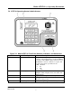
Figure 7-0. Model ATRT-01 Front-Panel Controls, Indicators, and Connectors .............................7
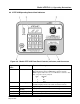
Figure 8-0. Model ATRT-01B Front-Panel Controls, Indicators, and Connectors...........................8
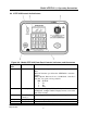
Figure 9-0. Model ATRT-01D Front-Panel Controls, Indicators, and Connectors ..........................9
Figure 16-0 Start-up menu ............................................................................................................12
Figure 16-1 ATRT-01 Menu Diagram...........................................................................................13
Figure 17-0 Transformer Selection menu......................................................................................15
Figure 18-0. Nameplate Voltage Selection Menu .........................................................................16
Figure 19-1. H-Winding Voltage Entry Display............................................................................17
Figure 19-2. H-Winding Voltage Entry Display............................................................................17
Figure 19-3. X-Winding Voltage Entry Display............................................................................17
Figure 19-4. X-Winding Voltage Entry Display............................................................................17
Figure 20-0. Start Test Screen......................................................................................................19
Figure 21-0. Test Result Display...................................................................................................20
Figure 22-0. Cable Connection Display........................................................................................21
Figure 23-0. Time and Date Display ............................................................................................22
Figure 24-0. Select Computer Interface Display..........................................................................23
Figure 25-4 Quick Test Menu .......................................................................................................28
Figure 25-5A Preset Voltage Menu...............................................................................................28
Figure 25-5B Test Result Menu ....................................................................................................28