
User guide


Model ATRT-01 (v) Operating Instructions
Rev 02
May 02, 2002
8
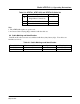
8.0 ATRT-01B Operating Control And Indicators
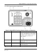
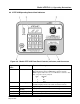
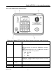
Figure 8-0. Model ATRT-01B Front-Panel Controls, Indicators, and Connectors
Fig. 8-0
Index
Panel Markings Functional Description
1
RS-232C Computer-Interface port, 9-pin, female DB type connector; This
RS-232C interface allows ATRT-01B to interface with an
IBM computer. Data rate is set to 19,200 baud, 1 start bit, 8 data
bits, 2 stop bits, and no parity bit.
PIN SIGNAL
2 Tx
3 Rx
5 Gnd
2
None (display) LCD: 4 line by 20 character screen; backlighted, sunlight
readable; Displays menus, test results, and status readouts.
3
None (H & X) High voltage and Low voltage connector, 16-pin male.
4
120/220Vac, 1A,
50/60Hz
Input power connector with third-wire safety ground.
5
None (Keypad) Pushbutton operating controls, 16-keys.
6
POWER Power Switch, Momentary contact.