
Owner's manual
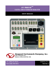

REV 2 CT-7500 S2 USER’S MANUAL
2
1.0 INTRODUCTION
1.1 General Description and Features
The CT-7500 S2 is an easy to use, stand-alone, microprocessor-driven EHV circuit-breaker
analyzer. It can operate either in Time-Travel analyzer mode or in Quick-Shot mode (for on-line
timing). In Time-Travel mode, the CT-7500 S2 can fully analyze a circuit-breaker’s performance
by testing the contact time, stroke, velocity, over-travel, and contact wipe. Contact-motion
analysis can be performed for all breaker contact operations (Open, Close, Open – Close, Close
– Open, and Open – Close – Open). The CT-7500 S2’s timing window is selectable between 1-
second, 10-second, or 20-second periods. The 10-second and 20-second timing windows are
ideal for timing long duration events such as circuit-switcher contact testing.
Quick-Shot Mode
In Quick-Shot mode, the CT-7500 S2 captures the breaker’s trip or close time, the trip/close-coil
current “fingerprint,” and the battery supply voltage while the breaker is still in service. The
trip/close time is derived from the time of trip, or close-coil initiation, to the breaker’s bushing
current-break-or-make as detected by an AC clamp-on current sensing probe.
With a simple connection (see Figure 11), the Quick-Shot mode can detect a breaker’s
operating conditions with little or no down time. In Quick-Shot mode, the first trip operation
time of the breaker is captured. If a breaker has been in service for a long period of time and
sitting in close position, the first trip time of the breaker may be slow possibly due to a sticky
mechanism. The Quick-Shot mode is very useful in such cases because traditional breaker
timing may not detect this condition since several operations may have occurred before the
first timing test is conducted.
Conventional Time-Travel Analysis Mode
The CT-7500 S2 is available in models with either 3 (CT-7500-3 S2), 6 (CT-7500-6 S2), or 12 (CT-
7500-12 S2) dry-contact inputs. All models feature three digital travel transducer input
channels.
Contact Timing Inputs
Dry-contact input channels are used for timing breaker contacts. Each contact input channel
can detect main contact and insertion-resistor contact times in milliseconds and cycles.
Voltage Monitoring Inputs
One analog voltage input channel, designated as V1, is dedicated to monitoring a circuit-
breaker’s DC power supply or coil voltage (0 – 255 volts, DC or peak AC). A second voltage input
channel, designated as V2, is dedicated to detecting the voltage on/off status (presence or
absence) of an A/B switch.