
User's Manual

©Vantage, 41127 / IS-0572-1 / InFusion Thermostat Interface Stations — MODELS: CC-WLINT & CC-RLINT page 1 of 2
Configure Button
INSTALLATION
VANTAGECONTROLS.COM VANTAGE INSTALL GUIDES
1061 South 800 East • Orem, Utah 84097 • Telephone 801 229 2800 • Fax 801 224 0355
Thermostat Interface Stations — MODELS: CC-WLINT & CC-RLINT
Overview
CC-WLINT, WireLink™ or CC-RLINT, RadioLink® thermostat
interface stations provide bi-directional communication
between the Vantage InFusion system and the CC-STAT
connected to the HVAC system. The new thermostat and
interface stations are backward* compatible.
Common Control and Feedback Features
• Display internal/remote temperature in fereinhiet or celcius
• Display external/outdoor temperature
• Display and control heat setpoint
• Display and control cool setpoint
• Display and control operation mode –
o Heat
o Off
o Cool
o Auto
• Display and control fan mode –
o On
o Auto
• Display and control network connection status –
o Connected (day mode) – no message
o Disconnected (night mode) – Network Override
• Maintains separate Network Override (night mode) heat
and cool setpoints.
o Network Override setpoints must be set from the
thermostat while in night mode.
• Display and/or condition on current call for heat
• Display and/or condition on current call for cool
• Display time and date
*NOTE: The CC-STAT thermostat will not work with the
Q-ETS3-WireLink or STHERR101-RadioLink interface stations.
However, an existing Vantage system (InFusion or QLink) with
an older thermostat and Q-ETS3 or STHERR101 can be
updated by replacing with a new CC-STAT and CC-WLINT or
CC-RLINT, adding the new serial number to the project file and
then updating the controller. No additional programming is
required unless wanted.
Specifications
Specifications
CC-WLINT
WireLink
CC-RLINT
RadioLink
Dimensions HWD
(minus wires,
antenna, and
shrink-wrap)
1.5” x 1.875” x 0.375”
38mm x 48mm x 10mm
1.5” x 1.875” x 0.375”
38mm x 48mm x 10mm
Weight approx. 0.8oz / 23g
Power connections
24Vac from HVAC or other 24Vac source
connected to the thermostat base
Station Count
Design Center
0.36W on IC-24
0.54W on IC-36
1 RadioLink Station
Station Count
QLink
1 WireLink Station 1 RadioLink Station
LED Indicators
WireLink/RadioLink connection status and,
receive, transmit LEDs
Station Bus Wiring
2C, 16AWG / 1.31mm2, twisted, non-shielded,
<30pF per foot. Separate a minimum of 12" /
30.5cm from other parallel communication
and/or high voltage runs.
Ambient Operating
Temperature
32-95°F -or- 0-35°C
Ambient Operating
Humidity
5-95% non-condensing
Software/Firmware
Vantage’s CC-WLINT & CC-RLINT thermostat interface
stations are compatible with InFusion Design Center software
and QLink (see NOTE above). Whenever possible it is
recommended that firmware and software be kept to the most
current release.
Installation
Installation of Vantage products should be performed or
supervised by a Certified Vantage Installer. The CC-WLINT
connects to the Vantage System Station Bus. The Station Bus
wire should comply with Vantage’s Station Bus wiring
specification. The CC-RLINT connects to the Vantage System
via a RadioLink enabled system.
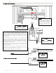
Mounting the CC-WLINT or CC-RLINT
The CC-WLINT or CC-RLINT may be mounted behind the
thermostat in a single gang box or may hang through a small hole
in the wall. Attach wires following the wiring diagram later in this
document. The CC-WLINT or CC-RLINT stations do not supply
power to the thermostat. Please see the Vantage Comfort &
Control Communicating Thermostat Installation Manual for
complete thermostat or humidistat installation.
Configuration
When the CC-WLINT or CC-RLINT is properly connected and
powered the status LED will have a two blink pattern for the
WireLink model or a three blink pattern for the RadioLink
model which typically means it is not configured. NOTE: The
LCD screen does not indicate that it is not configured. From
Design Center, with the station highlighted, click on the
Configure Stations button on the toolbar menu and wait for
the station to display the following scrolling message, PRESS
HOLD TO CONFIGURE / VANTAGE CONFIGURATION. Press
and release the HOLD button, wait for one or two seconds, and
verify that the serial number was populated in Design Center.
Repeat if necessary. Two additional ways to configure: 1)
Follow the steps above but press the configure button on the
CC-WLINT or CC-RLINT station. The button is located on the
same side as the LED lights, near the middle of the board as
illustrated below. The button may be pressed by pressing the
shrink-wrap directly over the button. 2) The station may also
be configured by typing the serial number in the project file,
using this method the station will automatically be configured
when the system is programmed. Once configured the status
LED on the CC-WLINT or CC-RLINT will blink evenly.
Status LED Diagnostic Information
During setup and configuration the CC-WLINT or CC-RLINT
status LED will blink at different intervals. The STATUS LED
blinks evenly or flashes 2, 3, 4, 5, or 6 times followed by a
pause to indicate status information.
One Even blink: The CC-WLINT or CC-RLINT is correctly
configured.
Two blinks: CC-WLINT or CC-RLINT is operating correctly but
is not configured.
Three blinks: CC-WLINT or CC-RLINT is not communicating
with the Controller. Verify that station bus wiring conforms to
Vantage guidelines or for CC-RLINT, verify that the serial
number is correct in the software and is in communication
range with the RadioLink Enabler.
Four blinks: CC-WLINT or CC-RLINT Factory problem; please
contact the factory.
Five blinks: CC-WLINT or CC-RLINT is in configuration mode.
Six blinks: Thermostat is not connected to the base.
Off: The Thermostat is not powered and/or the CC-WLINT or
CC-RLINT station is not properly wired.