
Installation Sheet


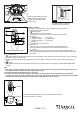
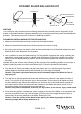

For LED module replacement only:
Separate the male from female terminals on the wires connecting the LED module to motor.
Take a new LED module and connect the white (neutral) wire from fan motor assembly to
the white (neutral) wire from the LED module and connect the blue (hot) wire from fan motor
assembly to the black (hot) wire from LED module.
Fig.8
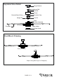
Connect the white (neutral)
wire from motor to the white
(neutral) wire from the
outlet box with a wire
connector.
Connect the black (hot) wire
(This is for fan and light control)
from motor to the black (hot) wire
from outlet box with a wire
connector.
Bla
Black
ck
Green
White
White
Grounding
Green
*** After making the wire connections, the wires should
be spread apart. The white (neutral) conductor and
green (grounding) conductor on one side and the
black (hot) conductor on the other side of the outlet
box.
*** The wire connection points should be turned upward
and pushed carefully up into outlet box.
Connect three
ground wires (Green
or bare copper) coming
from outlet box,
downrod and hanging
bracket with a wire
connector.
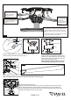
Slide the canopy up to ceiling and over the two
canopy screws on hanger bracket. Rotate canopy
clockwise, next, while holding the canopy with one
hand, slide the canopy cover over the screws and
rotate counterclockwise until tight.
Note: Adjust the canopy screws as necessary
until the canopy and canopy cover are snug.
Tighten blades to blade brackets by using blade holder screws and washers.
Note: The blades shape should be same with the blade holders shape. (Fig.11a)
Canopy Screw
Hanger Bracket
Canopy
Canopy Cover
Fig.10
Blade Holder
Blade
Washers
Blade Holder
Screws
Fig.11
PAGE: 6 / 9
Fan Motor
Assembly
LED Module
LED Module
Screw
Female Terminal
Male Terminal
Fig.12
Hang the safety cable into the safety cable hook, tighten the safety
cable to the safety cable hook by using the zip-tie.
Fig.11a
Safety Cable Hook
Safety Cable
Zip-tie
Fig.9
210413